
very good!


KEY SPECS · EVE POWER MB31
SOURCE [1]- SIZE
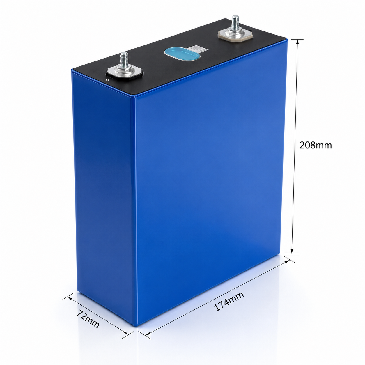
- 173.7 × 71.7 × 207.2 mm
- nominal ±0.5 / ±0.8 / ±0.5 · with insulation film; H1 with terminal
- CAPACITY
- 314 Ah typ.
- min. not stated by manufacturer
- 0.5P/0.5P, 25±2 °C, 2.5-3.65 V
- TEMPERATURE
- −30 to 60 °C
- discharge · cell surface
- charge 0 to 60 °C · cell surface
[1] Product Specification, Prismatic LFP Cell, Model MB31, Version A, on file since 2024-04-16
EVE · PRISMATIC LiFePO4 · MB31 · PACK OF FOUR
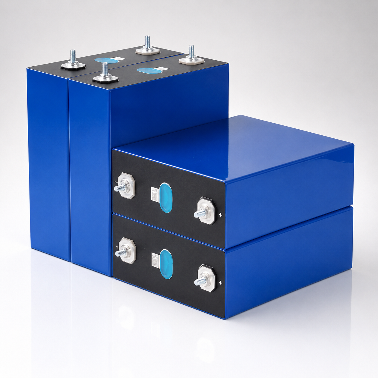
Four EVE MB31 prismatic LFP (LiFePO4) cells, sold as a pack with busbars included. Every rating on this page is per cell, from EVE’s specification [1]: 3.2 V nominal; Nominal Capacity 314 Ah and Nominal Energy 1,004.8 Wh at “0.5P / 0.5P, 25°C ± 2°C, 2.5 V ~ 3.65 V” (charged and discharged at 0.5P), “Fresh cell”; and charge and discharge limits in power, not amps: 0.5P continuous at “25°C ± 2°C”, 502.4 W for a fresh cell (0.5P × 1,004.8 Wh, our arithmetic). Below: each rating with its condition and the table and page it comes from, and each calculation with its formula. The documents themselves aren’t linked; the questions in section 12 say why.
NOMINAL CAPACITY · PER CELL314 AhNominal Energy 1,004.8 Wh; “0.5P / 0.5P, 25°C ± 2°C, 2.5 V ~ 3.65 V”, “Fresh cell” [1] Table 2; minimum: not stated by manufacturer
NOMINAL VOLTAGE · PER CELL3.2 V[1] Table 2; four in series, calculated: 4 × 3.2 V = 12.8 V, 4 × 1,004.8 Wh = 4,019.2 Wh
MAX. CONTINUOUS DISCHARGING POWER · PER CELL0.5P“25°C ± 2°C” [1] Table 2; 502.4 W for a fresh cell, calculated: 0.5P × 1,004.8 Wh
MAX. CONTINUOUS CHARGING POWER · PER CELL0.5P“25°C ± 2°C” [1] Table 2; charge to 3.65 V
CYCLE LIFE · CYCLES · PER CELL8,000“8000 cycles, 70% SOH”, “25°C Cycle”, cells clamped [1] Table 3
WEIGHT · PER CELL5,600 g± 300 g [1] Table 2
PRISMATICLiFePO44 CELLS · BUSBARSBARE CELLSNO BMS
Bare cells: components for protected packs and devices built for them. Not for vaping. Charge on a LiFePO4 charger or BMS set to 3.65 V per cell.
01SPEC PLATE
Every rating, per cell, with its condition.
EVE’s Product Specification for the MB31 [1] rates one cell; this page calls it the specification. Its figures come first, copied as printed with the table and printed page they sit on. Then the test criteria and limits its other tables print, our arithmetic, and what the transport papers [2]–[9] record. Each row names its source or shows its formula. The pack of four has no ratings of its own (section 09).
| ITEM | VALUE | CONDITION · SOURCE |
|---|---|---|
| PRINTED IN THE SPECIFICATION · PER CELL copied as printed, with table and printed page [1] | ||
| MODEL | MB31 | “Prismatic LFP Cell” (lithium iron phosphate, LiFePO4), Specification No. PBRI-MB31-D06-01, Version A [1] cover |
| CAPACITY, NOMINAL | 314 Ah | “0.5P / 0.5P, 25°C ± 2°C, 2.5 V ~ 3.65 V”, “Fresh cell” [1] Table 2, p.1 |
| CAPACITY, MINIMUM | — | Not stated by manufacturer [1] |
| ENERGY, NOMINAL | 1,004.8 Wh | “0.5P / 0.5P, 25°C ± 2°C, 2.5 V ~ 3.65 V”, “Fresh cell” [1] Table 2, p.1 |
| NOMINAL VOLTAGE | 3.2 V | [1] Table 2, p.1 |
| END-OF-CHARGE VOLTAGE | 3.65 V | where the standard charge stops [1] Table 2, p.1; Table 4, p.3 |
| END-OF-DISCHARGE VOLTAGE | 2.5 V | “2.5 V(T >0°C)”; “2.0 V(T ≤0°C)”; Table 2 doesn’t say whether T is the cell or the ambient temperature [1] Table 2, p.1 |
| MAX. CONTINUOUS CHARGING POWER | 0.5P | “25°C ± 2°C”; 502.4 W for a fresh cell, CALCULATED: 0.5P × 1,004.8 Wh [1] Table 2, p.1; Table 4, p.3 |
| MAX. CONTINUOUS DISCHARGING POWER | 0.5P | “25°C ± 2°C”; 502.4 W for a fresh cell, CALCULATED: 0.5P × 1,004.8 Wh [1] Table 2, p.1; Table 6, p.4 |
| STANDARD CHARGE | 502.4 W | “Charge to 3.65 V with a constant power of 502.4 W”; Standard Charging Power 0.5P, “25°C ± 2°C” [1] Table 4, p.3 |
| STANDARD DISCHARGE | 502.4 W | “Discharge to 2.5 V with a constant power of 502.4 W”; Standard Discharging Power 0.5P, “25°C ± 2°C” [1] Table 6, p.4 |
| CURRENT RATING | — | Not stated by manufacturer: [1] gives charge and discharge only in P, a power rate, and prints no pulse rating; amps at 0.5P are calculated in section 03 |
| CHARGING TEMPERATURE | 0 to 60 °C | Table 2 names no basis; Table 5 prints 0.05P at 0 °C and 0 at 60 °C cell temperature [1] Table 2, p.2; Table 5, p.4 |
| DISCHARGING TEMPERATURE | −30 to 60 °C | Table 2 names no basis; Table 7 prints 0 at −30 °C and 60 °C cell temperature [1] Table 2, p.2; Table 7, p.5 |
| ABSOLUTE CHARGING TEMPERATURE | 0 to 60 °C | cell temperature, “0°C ~ 60°C”: outside it, “stop charging” [1] Table 4, p.4 |
| ABSOLUTE DISCHARGING TEMPERATURE | −35 to 65 °C | cell temperature, “-35°C ~ 65°C”: outside it, “stop discharging” [1] Table 6, p.5 |
| ABSOLUTE CHARGING VOLTAGE | 3.8 V | “Max 3.8 V”: above it, stop charging [1] Table 4, p.4 |
| ABSOLUTE DISCHARGING VOLTAGE | 1.8 V | “Min 1.8 V”: below it, stop discharging [1] Table 6, p.5 |
| INITIAL INTERNAL RESISTANCE | 0.18 ± 0.05 mΩ | “AC, 1 kHz, Delivery SOC,” “Fresh cell” (SOC: state of charge); an AC figure, not a DC resistance [1] Table 2, p.1 |
| SELF-DISCHARGE | ≤ 3.5 % / M | “⩽3.5% / M” in the “First Month”, “⩽3.0% / M” “After First Month”; “Delivery SOC status, 25°C ± 2°C storage”; [1] doesn’t define M, a month is implied [1] Table 2, p.2 |
| CELL TEMPERATURE RISE | ≤ 10 °C | “25°C, 0.5P, discharge”: the change in cell surface temperature over the discharge [1] Table 3, p.3 |
| CYCLE LIFE | 8,000 cycles | “8000 cycles, 70% SOH”, “25°C Cycle”: clamped cells, 502.4 W between 3.65 and 2.5 V, power lowered as the cell ages [1] Table 3, p.3; Appendix 2 §1.15, pp.27–28 |
| STORAGE TEMPERATURE | 0 to 35 °C | “1 year”; −20 to 45 °C for “1 month”; “Delivery SOC status” [1] Table 2, p.2 |
| HEIGHT H1 | 207.2 ± 0.5 mm | “With Terminal”; all dimensions “With insulation film” [1] Table 2, p.1 |
| HEIGHT H2 | 204.6 ± 0.5 mm | “Without Terminal” [1] Table 2, p.2 |
| LENGTH L | 173.7 ± 0.5 mm | [1] Table 2, p.2 |
| THICKNESS T | 71.7 ± 0.8 mm | “(300 kgf ± 20 kgf compression force, Delivery SOC)” [1] Table 2, p.2 |
| POLE CENTER DISTANCE | 123.0 ± 0.3 mm | [1] Table 2, p.2; the Fig. 15 drawing prints “123.0 ±0.5” (Appendix 1, p.19) |
| WEIGHT | 5,600 ± 300 g | [1] Table 2, p.1 |
| POLES | Ø14 welding area | Fig. 15: “Ø14焊接区域”, “焊接深度 max 2mm” (welding area; welding depth max 2 mm, our translation); “Max Torque on Poles” “6 N·m”, “Max Pressure on Poles” “700 N”; no stud, thread or bolt size printed [1] Appendix 1, p.19; Table 11, p.10 |
| BMS · PROTECTION | None included | as sold: four bare cells and busbars. EVE’s specification asks for a battery management system that monitors, manages and protects each cell, to the limits of Tables 9 and 10 [1] §4.1, §4.4, p.7 |
| + Source: [1] EVE Power Co., Ltd., “Product Specification”, “Prismatic LFP Cell”, “Model: MB31”, Specification No. PBRI-MB31-D06-01, Version A, “Nov. 2023” (as printed; revision A dated 2023-11-20, printed “2023.11.20”; 39 pages), the only version we hold; EVE may revise it (§6). On file and quoted on this page, not linked, because EVE marks every page “-EVE Power CO., LTD Confidential Proprietary-” and its §8.3 is a confidentiality clause. Page numbers are as printed: i–vi, then 1–32. Call or text us with questions about its figures. | ||
| ITEM | VALUE | CONDITION · SOURCE |
|---|---|---|
| PRINTED IN THE SPECIFICATION’S TABLES test criteria and limits as printed, per cell [1] | ||
| ENERGY EFFICIENCY AT 0.5P | ≥ 93.5 % | “E₁*/E₁ ≥ 93.5%”: discharge ÷ charge energy at 502.4 W, “25°C ± 2°C” ambient [1] Table 3, p.2; Appendix 2 §1.11 |
| ENERGY, 45 °C AMBIENT (TEST) | ≥ 98 % of E₀* | “E₄* ≥ 98%*E₀*”; efficiency “E₄*/E₄ ≥ 93%”; after 5 h at 45 °C ambient. E₀* is each cell’s own calibration energy, not 1,004.8 Wh [1] Table 3, p.2; §1.12.1 |
| ENERGY, 5 °C AMBIENT (TEST) | ≥ 80 % of E₀* | “E₅* ≥ 80%*E₀*”; efficiency “E₅*/E₅ ≥ 76%”; after 5 h at 5 °C ambient [1] Table 3, p.2; §1.12.2 |
| RETENTION · 25 °C, 28 DAYS | ≥ 95 % of E₀* | “25°C & 28 days” from 100 % SOC: “E₆* ≥ 95%*E₀*”; recovery “E₇* ≥ 97%*E₀*” [1] Table 3, pp.2–3; §1.13.1 |
| RETENTION · 45 °C, 7 DAYS | ≥ 95 % of E₀* | “45°C & 7 days”: “E₈* ≥ 95%*E₀*”; recovery “E₉* ≥ 97%*E₀*” [1] Table 3, pp.2–3; §1.13.2 |
| STORAGE · 25 °C, 28 DAYS | ≥ 98 % of E₀* | “25°C & 28days” at 50 % SOC: discharging energy recovery “≥ 98%*E₀*” [1] Table 3, p.3; §1.14.1 |
| STORAGE · 45 °C, 28 DAYS | ≥ 97 % of E₀* | “45°C & 28days” at 50 % SOC: “≥ 97%*E₀*” [1] Table 3, p.3; §1.14.2 |
| SWELLING FORCE | ≤ 50,000 N | at “70% SOH”; “≤ 60000 N” at “60% SOH”; in the swelling-force clamp [1] Table 3, p.3; §1.16 |
| RECOMMENDED COMPRESSION FORCE | 3,000–7,000 N | “3000 N ~ 7000 N”, §4.6 test conditions; “Instantaneous maximum compression force” “≤ 10000 N” [1] Table 13, p.11 |
| RECOMMENDED OPERATING TEMPERATURE | 10 to 45 °C | “Recommended cell using temperature range” [1] Table 10, p.9 |
| MAXIMUM SAFE TEMPERATURE | 65 °C | and −35 °C minimum safe; §5: the cell “shall not exceed 65°C in any normal use” [1] Table 10, p.9; §5, pp.13–14 |
| BMS CHARGE CAPACITY LIMIT | < 354.8 Ah | “Charging capacity < 354.8 Ah”, “The charging capacity shall be less than 113% of the nominal capacity.” [1] Table 9, p.8 |
| END OF LIFE | 60 % capacity | stop using a cell below 60 % of nominal capacity, or above 150 % of its initial internal resistance [1] §3, p.6 |
| THERMAL CONDUCTIVITY | 9–11 W/(m·K) | “X/Z direction”; “2 ~ 3 W/(m·K)” in the “Y direction” (the thickness); heat capacity “0.9 ~ 1.1 kJ/(kg·K)” [1] Table 14, p.12 |
| CALCULATED arithmetic on [1], shown so you can check it | ||
| 0.5P IN WATTS, FRESH CELL | 502.4 W | 0.5P × 1,004.8 Wh; [1] prints this example in its Term Definition, p.iv |
| CURRENT AT 0.5P, 3.65 V | 137.6 A | 502.4 W ÷ 3.65 V; not a rating |
| CURRENT AT 0.5P, 3.2 V | 157.0 A | 502.4 W ÷ 3.2 V; not a rating |
| CURRENT AT 0.5P, 2.5 V | 201.0 A | 502.4 W ÷ 2.5 V, the cut-off at T > 0 °C; not a rating |
| CURRENT AT 0.5P, 2.0 V | 251.2 A | 502.4 W ÷ 2.0 V, the cut-off at T ≤ 0 °C; not a rating |
| CAPACITY AT 70 % SOH | 219.8 Ah | 70 % × 314 Ah, the cycle-life end point; 60 % × 314 Ah = 188.4 Ah, the end of life |
| FOUR CELLS IN SERIES, 4S | 12.8 V | 4 × 3.2 V nominal; 4,019.2 Wh = 4 × 1,004.8 Wh (section 09) |
| VOLUME | 2,548 cm³ | 173.7 mm × 71.7 mm × 204.6 mm ≈ 2,548,148 mm³ ≈ 2,548 cm³: the box L × T × H2 around the case without poles, at the printed sizes, with insulation film, T at “(300 kgf ± 20 kgf compression force, Delivery SOC)”; 2,506–2,590 cm³ across the Table 2 tolerances |
| FROM THE TRANSPORT PAPERS cited by number, laboratory and date; not posted [2]–[9] | ||
| UN38.3 TEST REPORT | 0111230000 |
Guangzhou Customs District Technology Center, dated 2024-01-15: T.1–T.6 and T.8 “Passed”, T.7 “Not applicable”, as printed [2]; summary 01112300005127-2(E) [3] |
| TRANSPORT IDENTITY | UN 3480 · Class 9 | [4][7]–[9]; proper shipping name “Lithium ion batteries”, as printed [7]–[9] |
| HAZARD CLASSIFICATION | 0111230000 |
2024-01-15; printed validity one year from issue, which has ended [4] |
| TRANSPORT CERTIFICATES | air · sea · road | 01112300005127-6(E), 01112300005127-7(E), 01112300005127-8(E); printed validity “2024-01-15~2024-12-31”, ended; EVE’s carton of four bare cells, “Battery only” [7]–[9] |
| + Source: [1] EVE Power Co., Ltd., “Product Specification”, “Prismatic LFP Cell”, “Model: MB31”, Specification No. PBRI-MB31-D06-01, Version A, “Nov. 2023” (as printed; revision A dated 2023-11-20, printed “2023.11.20”; 39 pages), the only version we hold; EVE may revise it (§6). On file and quoted on this page, not linked, because EVE marks every page “-EVE Power CO., LTD Confidential Proprietary-” and its §8.3 is a confidentiality clause. Page numbers are as printed: i–vi, then 1–32. Call or text us with questions about its figures. + Source: [2] Guangzhou Customs District Technology Center, UN38.3 Test Report No. 01112300005127-1(E), model MB31, dated 2024-01-15 (no version printed; “Test date” 2023-12-08~2024-01-15); applicant EVE Power Co., Ltd.; on file, not posted + Source: [3] Guangzhou Customs District Technology Center, UN38.3 test summary No. 01112300005127-2(E), 2024-01-15 (no version printed), summarizing [2]; on file, not posted + Source: [4] Guangzhou Customs District Technology Center, hazard classification report No. 01112300005127-3, 2024-01-15 (in Chinese; no version printed); printed validity one year from issue, which has ended; it classified the MB31 samples submitted; on file, not posted + Source: [5] Guangzhou Customs District Technology Center, Material Safety Data Sheet No. 01112300005127-4(E), 2024-01-15 (no version printed); prints no rating and gives no figure on this page; on file, not posted + Source: [6] Guangzhou Customs District Technology Center, label audit report No. 01112300005127-5, 2024-01-15 (in Chinese; no version printed); valid only together with [4], whose printed validity has ended; on file, not posted + Source: [7]–[9] Guangzhou Customs District Technology Center, transport certificates for air, sea and road, Nos. 01112300005127-6(E), 01112300005127-7(E) and 01112300005127-8(E), issued 2024-01-15 (no version printed); printed validity “2024-01-15~2024-12-31”, which has ended; they covered EVE’s own carton of four bare cells (“Battery only”), not this pack with busbars; on file, not posted | ||
PRINTED IN [1]FIG 1.1
Voltage window, per cell
Capacity window 2.5–3.65 V · “2.5 V ~ 3.65 V”, Table 2
Nominal 3.2 V · Table 2
End of discharge 2.5 V at “T >0°C”, 2.0 V at “T ≤0°C” · Table 2
Charge regularly to stay above 2.8 V in normal use · §5
Absolute stop limits “Min 1.8 V” · “Max 3.8 V” · Tables 4 and 6
Per-cell voltages printed in [1], in volts. Orange: the window of Table 2’s capacity condition (p.1). Marks: its 3.2 V nominal and the end-of-discharge voltages; the absolute limits of Tables 4 and 6 (pp.4–5), beyond which charging or discharging stops; and §5’s “charge the cell regularly to keep the voltage above 2.8 V” (p.13). Table 2 doesn’t say whether T is the cell or the ambient temperature. BMS levels: fig 5.1 and fig 5.2.
PRINTED IN [1]FIG 1.2
Temperature ranges, as each table prints them
Charging, Table 2 0 to 60 °C · no basis printed
Discharging, Table 2 −30 to 60 °C · no basis printed
Absolute charging, cell temperature 0 to 60 °C · charging stops outside · Table 4
Absolute discharging, cell temperature −35 to 65 °C · discharging stops outside · Table 6
Recommended, cell temperature 10 to 45 °C · Table 10
Table 10 limits power to 0 below −30 °C and above 60 °C; safe limits −35 °C and 65 °C
Temperature ranges printed in [1], in °C. Gray: Table 2’s charging and discharging ranges (p.2), which name no basis. Black: the absolute ranges of Tables 4 and 6 (pp.4–5), in cell temperature; outside them, charging or discharging stops. Orange: Table 10’s “Recommended cell using temperature range” (p.9). Marks: Table 10’s operating limits, beyond which “the cell power needs to be reduced to 0”, and its safe limits, beyond which it warns of “irreversible and permanent damage to the battery”. Cell temperature is read by a sensor at the center of the cell surface (Term Definition, p.iv). Power by cell temperature: fig 2.1 and fig 4.1.
PRINTED IN [1]FIG 1.3
Storage temperature, as printed
1 month −20 to 45 °C · “Delivery SOC status” · Table 2
1 year 0 to 35 °C · Table 2
Recommended, §4.9 0 to 25 °C, relative humidity ≤ 60 %
Storage temperatures printed in [1]: Table 2’s windows for “1 year” and “1 month” at “Delivery SOC status” (p.2), the state of charge at delivery, which [1] never quantifies, and §4.9’s recommended conditions, “0°C ~ 25°C, relative humidity ≤ 60%” (p.12), in orange. Storage charge and self-discharge: section 06 below.
02 · POWER
Power, not amps: 0.5P per cell at 25 ± 2 °C.
EVE rates the MB31’s charge and discharge as a power rate, written P: the charge or discharge power divided by the cell’s energy, as the battery system determines it from repeated readings (Term Definition, p.iv). 0.5P is a power of half the cell’s energy per hour, a rate that would empty a full cell in about two hours. Table 2 prints Max. Continuous Discharging Power 0.5P and Max. Continuous Charging Power 0.5P, both at “25°C ± 2°C”. For a fresh cell at the 1,004.8 Wh Nominal Energy, 0.5P is 502.4 W, the specification’s own example: “when the cell energy is 1004.8 Wh and the charge/discharge power is 502.4 W, the charge/discharge power is 0.5P”. As the cell ages and its energy falls, 0.5P is fewer watts. Section 03 below turns 0.5P into amps.
MAX. CONTINUOUS DISCHARGING POWER · PER CELL0.5P“25°C ± 2°C” [1] Table 2, p.1 · 502.4 W for a fresh cell, CALCULATED: 0.5P × 1,004.8 Wh
NOMINAL CAPACITY · ENERGY · PER CELL314 Ah1,004.8 Wh · “0.5P / 0.5P, 25°C ± 2°C, 2.5 V ~ 3.65 V”, “Fresh cell” [1] Table 2, p.1
PRINTED IN [1]FIG 2.1
Discharging power, by cell temperature
Max. discharging power, P
00.10.20.30.40.5−30−150153045600.5P0.5P00not printed
Cell temperature, °C
Data: [1] §2.4.2 Table 7, Continuous Discharging Rate (unit: P-Rate), p.5 · max discharging power in P · “0% ~ 100% SOC” · cell temperature · points at the ten printed columns only. Table 7 prints no column between 5 and 45 °C, so that span is a gap, and none between −30 and −20 °C, so the chart doesn’t show where 0 becomes 0.5P. Table 2’s 0.5P is printed at “25°C ± 2°C” without saying whether that is cell or ambient temperature, so it isn’t plotted · the solid axis line sits at −0.1P; P = 0 is the dotted line above it · 0.5P × 1,004.8 Wh = 502.4 W for a fresh cell, CALCULATED · data table under fig 4.1
03POWER AND CURRENT
What 0.5P means in amps.
[1] prints no current rating. In its standard modes the cell charges and discharges at a constant 502.4 W (Tables 4 and 6), so the current rises as the voltage falls. The amps below are our arithmetic, I = 502.4 W ÷ V, for a fresh cell; they are not ratings.
CALCULATED FROM [1]FIG 3.1
Current at 0.5P, by cell voltage
I = 502.4 W ÷ V, at the voltages Table 2 prints (p.1), for a fresh cell at 1,004.8 Wh. Our arithmetic, not a rating: [1] gives charge and discharge in power and prints no current. At constant power the current rises as the voltage falls. Orange: 251.2 A at 2.0 V, the end-of-discharge voltage at T ≤ 0 °C, where Table 7 (cell temperature) still prints 0.5P at its columns down to −20 °C (−20, −10, −5 and 0 °C). Bars start at zero.
DATA TABLE · FIG 3.1
| VOLTAGE | WHERE [1] PRINTS IT | A AT 502.4 W | FORMULA |
|---|---|---|---|
| 3.65 V | End-of-charge Voltage, Table 2 | 137.6 | 502.4 ÷ 3.65 |
| 3.2 V | Nominal Voltage, Table 2 | 157.0 | 502.4 ÷ 3.2 |
| 2.5 V | End-of-discharge, T > 0 °C, Table 2 | 201.0 | 502.4 ÷ 2.5 |
| 2.0 V | End-of-discharge, T ≤ 0 °C, Table 2 | 251.2 | 502.4 ÷ 2.0 |
PRINTED IN [1] + CALCULATEDFIG 3.2
Cycle-test power, by SOH band
The charge and discharge power of the cycle-life test, printed for three state-of-health (SOH) bands in Appendix 2 §1.15 (pp.27–28). The Term Definition (p.iv) prints the first two as 0.5P at the energy where their band starts: 502.4 W when the cell energy is 1,004.8 Wh, and 401.92 W when it has fallen to 803.84 Wh. By our arithmetic, 351.68 W is 0.5P of a cell at 70 % of 1,004.8 Wh, 703.36 Wh. §1.15 holds each power across its band while the energy falls, so inside a band the rate rises above 0.5P, reaching 0.625P at the end of the first band (502.4 W ÷ 803.84 Wh, our arithmetic). Bars start at zero.
Reading a P rating
- P is the charge or discharge power divided by the cell’s energy, as the battery system determines it from repeated readings [1] (Term Definition, p.iv). In watts, 0.5P is the cell’s watt-hours divided by 2 h: 1,004.8 Wh ÷ 2 h = 502.4 W, so a full charge or discharge at 0.5P takes about 2 hours, by our arithmetic.
- For a fresh cell at 1,004.8 Wh, 0.5P is 502.4 W, the specification’s own example. An aged cell’s 0.5P is fewer watts: the cycle-life test steps down to 401.92 W and then 351.68 W (fig 3.2).
- [1] prints no current rating and no pulse rating. At a constant 502.4 W the current rises as the voltage falls, from 137.6 A at 3.65 V to 251.2 A at 2.0 V (CALCULATED, I = 502.4 W ÷ V; fig 3.1).
- Size wiring, fuses and BMS current limits for the low-voltage end, not for the nominal-voltage figure.
- Four cells in series carry the same current as one: a 4S pack of fresh cells at 0.5P is 4 × 502.4 W = 2,009.6 W, at the same 137.6–251.2 A (section 09).
- Table 3 also lists criteria at a 1P test rate (§1.11, “1004.8 W”), twice the 0.5P continuous rating; this page leaves them off.
04TEMPERATURE
Power, by cell temperature.
Two tables in [1] set the continuous power by cell temperature, read by a sensor at the center of the cell surface (Term Definition, p.iv): Table 5 for charging, Table 7 for discharging (fig 2.1). Both print columns at set temperatures only; where a column is missing, the charts leave a gap. Table 3 adds energy criteria at 45 and 5 °C ambient.
PRINTED IN [1]FIG 4.1
Charging power, by cell temperature
Max. charging power, P
00.10.20.30.40.501020304050600.05P0.12P0.3P0.5P0.5P0not printed
Cell temperature, °C
Data: [1] §2.3.2 Table 5, Continuous Charging Modes (unit: P-Rate), p.4 · “0% ~ 100% SOC” · cell temperature · points at the ten printed columns only; no column is printed between 25 and 45 °C, so that span is a gap · below 0 °C, no charging (Table 10, note b; our translation) · the solid axis line sits at −0.1P; P = 0 is the gray gridline above it · the table below also holds Table 7 (fig 2.1). *W = P × 1,004.8 Wh, a fresh cell, rounded to 0.1 W: CALCULATED.
DATA TABLE · FIG 4.1
| CELL TEMP. | CHARGING P, TABLE 5 | W charging, FRESH CELL* | DISCHARGING P, TABLE 7 | W discharging, FRESH CELL* |
|---|---|---|---|---|
| −30 °C | not printed | not printed | 0 | 0.0 |
| −20 °C | not printed | not printed | 0.5 | 502.4 |
| −10 °C | not printed | not printed | 0.5 | 502.4 |
| −5 °C | not printed | not printed | 0.5 | 502.4 |
| 0 °C | 0.05 | 50.2 | 0.5 | 502.4 |
| 5 °C | 0.12 | 120.6 | 0.5 | 502.4 |
| 10 °C | 0.3 | 301.4 | not printed | not printed |
| 15 °C | 0.5 | 502.4 | not printed | not printed |
| 20 °C | 0.5 | 502.4 | not printed | not printed |
| 25 °C | 0.5 | 502.4 | not printed | not printed |
| 45 °C | 0.5 | 502.4 | 0.5 | 502.4 |
| 50 °C | 0.5 | 502.4 | 0.5 | 502.4 |
| 55 °C | 0.5 | 502.4 | 0.5 | 502.4 |
| 60 °C | 0 | 0.0 | 0 | 0.0 |
PRINTED IN [1]FIG 4.2
Energy at 45 °C and 5 °C ambient (test)
Discharge energy, % of the cell’s own E₀*Energy efficiency, discharge ÷ charge
Criteria printed in Table 3 of [1] (p.2), each a ≥ bound: “E₄* ≥ 98%*E₀*” and “E₄*/E₄ ≥ 93%” at 45 °C, “E₅* ≥ 80%*E₀*” and “E₅*/E₅ ≥ 76%” at 5 °C, and “E₁*/E₁ ≥ 93.5%” at 0.5P. The 45 and 5 °C rows are ambient test temperatures: the cell rests 5 h at that temperature, then charges and discharges at 502.4 W (Appendix 2 §1.12, p.25). Their percentages are of each cell’s own E₀*, the average discharge energy of its calibration cycles (§1.10, p.24), not of 1,004.8 Wh, so they don’t convert to Wh. Bars start at zero.
Cold and heat
- Below 0 °C, don’t charge. Table 10 note b) (p.10), our translation (the specification says its Chinese version prevails, §6): no charging at low temperature, below 0 °C, and no discharging at the specified minimum safe temperature.
- At 0 °C cell temperature Table 5 prints 0.05P, 50.2 W for a fresh cell (0.05P × 1,004.8 Wh, our arithmetic), then 0.12P at 5 °C and 0.3P at 10 °C. It prints 0.5P at its columns from 15 to 25 °C (15, 20 and 25 °C) and from 45 to 55 °C (45, 50 and 55 °C), no column between 25 and 45 °C, and 0 at 60 °C (fig 4.1).
- Table 7 prints 0.5P at each discharging column from −20 to 5 °C (−20, −10, −5, 0 and 5 °C) and from 45 to 55 °C (45, 50 and 55 °C), and 0 at −30 and 60 °C (fig 2.1). It prints no column between 5 and 45 °C.
- Charging stops outside 0 to 60 °C cell temperature, discharging outside −35 to 65 °C (Tables 4 and 6). §5 (pp.13–14): “The temperature of the cell shall not exceed 65°C in any normal use, otherwise the BMS must shut down the cell and stop cell operation.”
- Table 10 recommends 10 to 45 °C cell temperature (p.9).
05CHARGING AND BMS
Charging, and the limits a BMS enforces.
EVE’s standard charge is constant power, 502.4 W to 3.65 V at “25°C ± 2°C” (Table 4). A pack of these cells needs a battery management system (BMS) that monitors, manages and protects each cell (§4.1); Table 9 prints the voltage levels it acts on (§4.4).
PRINTED IN [1]FIG 5.1
BMS levels, charging
Charging Ends · 3.65 V “When the cell voltage reaches 3.65 V, stop charging.”
Third level · 3.7 V “BMS alarms”
Second level · 3.75 V “Reduce cell charging current or power”
First level · 3.80 V “Cut off the current, force the cell to stop working and lock the BMS until the technician solves the problem.”
Charging levels per cell, as printed in Table 9 of [1] (§4.4, pp.7–8), with the printed action under each. EVE numbers the levels from the most severe, First, to the mildest, Third. The First level, 3.80 V, matches Table 4’s absolute charging voltage, “Max 3.8 V”. §4.4: “The design of the BMS shall meet the safety voltage and operating temperature limitations in Tables 9 and Table 10”.
PRINTED IN [1]FIG 5.2
BMS levels, discharging
Table 9, above 0 °C; Table 6 minimumTable 9, at or below 0 °C
Discharging Ends “2.5 V (> 0°C)” · “2.0 V (≤ 0°C)” · thresholds only, see the note
Third level “2.0 V (> 0°C)” · “1.9 V (≤0°C)” · “BMS alarms”
Second level “1.9 V (> 0°C)” · “1.8 V (≤ 0°C)” · “Reduce cell discharging current or power”
First level “1.85 V (> 0°C)” · “1.75 V (≤ 0°C)” · “Cut off the current, force the cell to stop working and lock the BMS until the technician solves the problem.”
Absolute minimum “Min 1.8 V” · Table 6
Discharging levels per cell, in volts, as printed in Table 9 of [1] (p.8): each Table 9 row prints a level above 0 °C (black mark) and one at or below 0 °C (gray mark); Table 9 names no temperature basis. EVE numbers the levels from the most severe, First, to the mildest, Third. For the Discharging Ends row we show the thresholds only: its printed action reads “stop charging”, in English and in Chinese, which doesn’t fit a discharging row. The Absolute minimum row’s black mark is Table 6’s “Min 1.8 V” (p.5), printed with no temperature condition, while Table 9’s First level at or below 0 °C is 1.75 V, as printed. Table 9 also prints “Short circuit is not allowed”: “When a short circuit occurs, the overcurrent protection device will disconnect the cell.”
Before you charge
- Use a LiFePO4 charger or BMS set to 3.65 V per cell: 4 × 3.65 V = 14.6 V for four in series, by our arithmetic.
- The standard charge is constant power, not constant current: “Charge to 3.65 V with a constant power of 502.4 W”, at “25°C ± 2°C” (Table 4, p.3). [1] prints no constant-voltage stage or termination current for it.
- Keep the charge within 0.5P at “25°C ± 2°C”, and at other temperatures within Table 5, which is in cell temperature (fig 4.1). No charging below 0 °C.
- Set the BMS to Table 9: stop at 3.65 V, alarm at 3.7 V, reduce at 3.75 V, cut off and lock at 3.80 V per cell (fig 5.1), and keep each charge below 354.8 Ah: “Charging capacity < 354.8 Ah” (p.8).
- Don’t leave cells low. §5: “charge the cell regularly to keep the voltage above 2.8 V”; Table 10 note a): “If the cell discharging voltage reaches the cut-off voltage, it is necessary to charge as soon as possible to prevent it from being over-discharged.”
- One model per battery system: “It is forbidden to mix different types of cells in the same battery system, otherwise, EVE will not be responsible for the quality assurance.” (§4.3)
06CYCLE LIFE AND STORAGE
What it keeps, cycled and stored.
[1] prints one cycle-life point, “8000 cycles, 70% SOH” at 25 °C, not a curve, and energy criteria after storage. It also prints two different storage charge ranges, in §4.9 and §4.10.
PRINTED IN [1] + CALCULATEDFIG 6.1
Cycle life and end of life, as printed
Start 100 % SOH = 314 Ah · SOH definition, p.v
80 % SOH 251.2 Ah, printed in the SOH definition · §1.15 steps the test power to 401.92 W here
After 8,000 cycles “8000 cycles, 70% SOH”, “25°C Cycle” · Table 3 · 70 % × 314 Ah = 219.8 Ah, calculated
End of life 60 % of nominal capacity, or 150 % of the initial internal resistance · §3 · 60 % × 314 Ah = 188.4 Ah, calculated
State of health (SOH) is the actual capacity over the 314 Ah nominal (Term Definition, p.v). [1] prints one cycle-life point: “8000 cycles, 70% SOH” in its “25°C Cycle” test, with cells clamped (§1.3.1), at 25 ± 2 °C ambient, charged at 502.4 W to 3.65 V and discharged at 502.4 W to 2.5 V with 30-minute rests, the power lowered to 401.92 W from 80 % SOH and 351.68 W from 70 % (Appendix 2 §1.15, pp.27–28). It prints no capacity between these points, so none is drawn. A figure EVE specifies for its own test conditions, not a warranty: [1] prints no warranty period or calendar life.
PRINTED IN [1]FIG 6.2
Energy kept after storage
Discharging energy retention, % of E₀*Discharging energy recovery, % of E₀*
Criteria printed in Table 3 of [1] (pp.2–3) after storage, each a ≥ bound: “25°C & 28 days” and “45°C & 7 days” from 100 % SOC (“E₆* ≥ 95%*E₀*”, “E₇* ≥ 97%*E₀*”; “E₈* ≥ 95%*E₀*”, “E₉* ≥ 97%*E₀*”), and “25°C & 28days” and “45°C & 28days” at 50 % SOC (“≥ 98%*E₀*”, “≥ 97%*E₀*”). E₀* is each cell’s own calibration energy (§1.10). Bars start at zero.
PRINTED IN [1]FIG 6.3
Storage charge, by clause
§4.9, storage “adjust the cell SOC to 30% ~ 40%”
§4.10, during storage “15% ~ 40%”; “perform a standard charge-discharge cycle every 3 months”
Table 3 storage tests 50 % SOC · §1.14
[1] prints two storage charge ranges (p.12): §4.9 says to “adjust the cell SOC to 30% ~ 40%” for storage, and §4.10 to keep it at “15% ~ 40%” during storage. Both are shown as printed; 30–40 % sits inside both. §4.10 also asks that the storage time after receiving the cells “should not exceed half a year”. Table 2’s storage windows and self-discharge are at “Delivery SOC status”, which [1] never quantifies.
PRINTED IN [1]FIG 6.4
Self-discharge, as printed
Self-discharge as printed in Table 2 of [1] (p.2), each a ≤ bound, “Delivery SOC status, 25°C ± 2°C storage”. [1] doesn’t define “M”; “First Month” implies a month. It prints no figure in mV per day. Bars start at zero.
07FIXTURE
Hold the cells under compression.
EVE gives the thickness under a “300 kgf ± 20 kgf” force (Appendix 2 §1.4), and its cycle-life test and most of its safety tests clamp each cell between steel plates (§1.3.1). §4.6: when forming modules, a compression force is applied across the thickness. The cells swell with use; Table 3 prints the force.
PRINTED IN [1]FIG 7.1
Compression and swelling force
Recommended compression “3000 N ~ 7000 N” · Table 13
Instantaneous maximum compression “≤ 10000 N” · Table 13
Swelling force at 70 % SOH “≤ 50000 N” · Table 3
Swelling force at 60 % SOH “≤ 60000 N” · Table 3
Forces printed in [1], per cell, in newtons. Orange: the recommended compression of Table 13 (p.11), applied in the “Y direction”, across the thickness, in the §4.6 test (p.10). Black: Table 3’s swelling force (p.3), the push on the clamp as the cell ages, recorded in the swelling-force clamp during the cycle test (Appendix 2 §1.16, §1.3.2); bars from zero to each printed ≤ bound. These are different forces: Table 13 is the compression you apply when assembling, and the note under it limits that to 10,000 N; Table 3’s swelling force is the push an aging cell builds against a clamp that holds it (§4.7, §1.16).
Fixture and assembly
- Press across the thickness, the Y direction of Fig. 12 (p.11), “in order to make them better arranged and fixed” (§4.6): “3000 N ~ 7000 N” recommended (Table 13). EVE’s test spreads it over “173.7 mm × 204.6 mm (L × H2)” at “15 % ~ 40 %” SOC. The note under Table 13: “The compression force of the cell shall be no larger than 10000 N, otherwise the cell may be damaged.”
- Table 2 gives the thickness at “300 kgf ± 20 kgf”: about 2,942 ± 196 N by our arithmetic (× 9.80665 N/kgf).
- Leave room to swell. §4.7 (pp.11–12): “it is suggested to reserve 2.0 mm ~ 2.5mm expansion space while grouping the cells”, and “the expansion force is about 60000 N when the cell capacity attenuates to 60% under the test conditions of 15 mm steel plate + 0.0 mm GAP (the space for cells to expand)”.
- Fig. 15 note (Appendix 1, p.19), our translation: the hatched band all the way round is a heat-affected zone, weaker than the base material; during assembly, end plates should press on the whole case face, to avoid stress concentration in that zone.
- Poles (Table 11, p.10): “Max Torque on Poles” “6 N·m” (the most torsion a pole takes without loosening), “Max Pressure on Poles” “700 N” (vertical, no deformation), “Max Temperature of Poles” “130°C” (before the plastic pad deforms). [1] prints no stud, thread or bolt size; whatever hardware you use, keep the torque on each pole within 6 N·m.
- §5: “It is forbidden to directly weld the cell.” Table 11 lists its “Laser Welding Depth” “≤ 2.0 mm” under “Welding Parameter of Al Busbar”, one of EVE’s recommended module welding parameters (§4.5), and Fig. 15 marks a Ø14 welding area on each pole. No EVE document covers the busbars in this pack or how they attach.
- §5: “Customer shall securely fix the cell to a solid surface and bind the power cord in a proper place to avoid arcing and sparks caused by friction.”
- Heat (Table 14, p.12): thermal conductivity “9 ~ 11 W/(m·K)” in the “X/Z direction” and “2 ~ 3 W/(m·K)” in the “Y direction”; heat capacity “0.9 ~ 1.1 kJ/(kg·K)”. §4.8 suggests reading the surface temperature at the poles or at the engraved code.
08SAFETY AND TRANSPORT
What the documents record.
Table 8 of [1] lists EVE’s own cell-level safety tests with methods and pass criteria; it prints no results. The UN38.3 report [2], from the Guangzhou Customs District Technology Center, records the transport tests on the samples EVE submitted. None of these papers covers the pack of four with busbars.
Safety tests the specification lists
| TEST | METHOD, CONDENSED FROM [1] | CRITERION, AS PRINTED | SECTION |
|---|---|---|---|
| Over-charge | Charged at 502.4 W to 3.65 V (§1.8) and clamped; then charged to 5.475 V, or for 1 hour, and watched for 1 hour. | “No fire, No explosion” | Table 8; App. 2 §1.17.1 |
| Over-discharge | Charged (§1.8) and clamped; then discharged to 0 V, or for 90 min, and watched for 1 hour. | “No fire, No explosion” | Table 8; App. 2 §1.17.2 |
| External Short-circuit | Charged (§1.8) and clamped; terminals shorted for 10 min through less than 5 mΩ; watched for 1 h. | “No fire, No explosion” | Table 8; App. 2 §1.17.3 |
| Crush Test | Charged (§1.8); crushed by a semi-cylinder of radius 75 mm at 5 ± 1 mm/s, perpendicular to the cell plate, until 0 V, 30 % deformation or 13,000 ± 780 N; held 10 min, watched 1 h. | “No fire, No explosion” | Table 8; App. 2 §1.17.4 |
| Drop Test | Charged (§1.8); dropped from 1.5 m onto concrete, terminals down; watched for 1 hour. | “No fire, No explosion” | Table 8; App. 2 §1.17.5 |
| Low Pressure | Charged (§1.8) and clamped; held at 11.6 kPa and 25 ± 2 °C for 6 h; watched for 1 hour. | “No leakage, No fire, No explosion” | Table 8; App. 2 §1.17.6 |
| Heating | Charged (§1.8) and clamped; heated at 5 °C/min to 130 ± 2 °C and held 30 min; watched for 1 hour. | “No fire, No explosion” | Table 8; App. 2 §1.17.7 |
| Thermal Runaway | Charged (§1.8) and clamped, then overcharged for a further 12 minutes; heated at 600–1,200 W until thermal runaway or 300 °C at the monitoring point; watched for 1 h. | “No fire, No explosion” | Table 8; App. 2 §1.17.8 |
Methods condensed from Appendix 2 §1.17 of [1] (pp.28–32), each referring to GB/T 36276-2018 (Lithium Ion Battery for Electrical Energy Storage); criteria as printed in Table 8 (pp.5–6). §2.5 adds: “The descriptions above only represent compliance at the cell level. The safety compliance at the module and the system level requires the customer to perform design verification.” The test currents are left off: they are abuse-test conditions, not ratings.
UN38.3 transport tests
| TEST | ITEM | RESULT, AS PRINTED [2] |
|---|---|---|
| T.1 | Altitude simulation | “Passed” |
| T.2 | Thermal test | “Passed” |
| T.3 | Vibration | “Passed” |
| T.4 | Shock | “Passed” |
| T.5 | External short circuit | “Passed” |
| T.6 | Crush | “Passed” |
| T.7 | Overcharge | “Not applicable” |
| T.8 | Forced discharge | “Passed” |
As printed in the results table of [2] (page 4 of 14): report 01112300005127-1(E), Guangzhou Customs District Technology Center, dated 2024-01-15, samples accepted 2023-12-08, “Test date” 2023-12-08~2024-01-15, method “ST/SG/AC.10/11/Rev.7/Amend.1, 38.3”. T.7 doesn’t apply to batteries or single-cell batteries without overcharge protection that are designed for use only as a component in another battery or in equipment that provides that protection (the report’s remark, condensed). The summary [3] marks assembled-battery testing “Not applicable”.
Transport papers
Transport identity, as printed: UN 3480, Class 9 [4][7]–[9]; proper shipping name “Lithium ion batteries” [7]–[9]. The air, sea and road certificates [7]–[9] (01112300005127-6(E), 01112300005127-7(E), 01112300005127-8(E), issued 2024-01-15) printed a validity of “2024-01-15~2024-12-31”, which has ended, and covered EVE’s own carton of four bare cells (“Battery only”), not this pack with busbars. The hazard classification report [4] (01112300005127-3, 2024-01-15) classified the submitted MB31 samples and printed a validity of one year from issue, which has ended. The MSDS [5] and the label audit [6] are dated 2024-01-15.
The report’s battery-information block lists declared currents of 157 A and 314 A, with no condition, duration or temperature; [1] rates the cell in power (0.5P) and prints no current rating, so this page follows [1].
None of [2]–[9] is posted on our site. Their footers bar quoting or reproducing them except in full, and several bar copying them at all, without the laboratory’s written permission, so this page cites them by number, date, laboratory, applicant and model, and gives only their test method, results, classification and printed validity, with three exceptions: the one sentence above on the report’s declared currents, the report’s remark on T.7, condensed, and the certificates’ scope, “Battery only”.
09PACK OF FOUR
Four cells in series: the arithmetic.
The listing is four cells with busbars. EVE’s specification defines a module as cells in series and parallel “after installing cell monitors and management devices” (Term Definition, p.v): four cells joined by busbars, with no monitor or BMS, are four cells, not a module. A battery built from them needs a BMS that monitors, manages and protects each cell (§4.1) to the limits of Tables 9 and 10 (§4.4). Every rating stays per cell; the figures below are arithmetic for one, two and four packs of four in series (4S, 8S, 16S), not pack ratings.
CALCULATED FROM [1]Arithmetic, not pack ratings
V NOMINAL3.2 × S
per-cell nominal voltage, 3.2 V, [1] Table 2, × S
V END OF CHARGE3.65 × S
per-cell end-of-charge voltage, 3.65 V, [1] Table 2, × S
V CUT-OFF2.5 × S
per-cell value at T > 0 °C, [1] Table 2, × S; 2.0 × S at T ≤ 0 °C
ENERGY · POWERE × S
per-cell E = 1,004.8 Wh nominal, [1] Table 2, × S; at 0.5P, 502.4 W × S for fresh cells
| CONFIG | CELLS | PACKS OF FOUR | V NOMINAL | V END OF CHARGE | V CUT-OFF, T > 0 °C | V CUT-OFF, T ≤ 0 °C | Wh NOMINAL | W AT 0.5P* | CELL MASS kg |
|---|---|---|---|---|---|---|---|---|---|
| 4S | 4 | 1 | 12.8 | 14.6 | 10.0 | 8.0 | 4,019.2 | 2,009.6 | 22.4 ± 1.2 |
| 8S | 8 | 2 | 25.6 | 29.2 | 20.0 | 16.0 | 8,038.4 | 4,019.2 | 44.8 ± 2.4 |
| 16S | 16 | 4 | 51.2 | 58.4 | 40.0 | 32.0 | 16,076.8 | 8,038.4 | 89.6 ± 4.8 |
CALCULATED FROM [1]FIG 9.1
Pack end-of-charge and cut-off voltages
End of charge, 3.65 V × SCut-off, 2.5 V × S at T > 0 °C
Per-cell voltages from Table 2 of [1] times the number of cells in series. At T ≤ 0 °C the cut-off is 2.0 V × S: 8.0, 16.0 and 32.0 V. Arithmetic, not pack ratings. Bars start at zero.
* W at 0.5P is the per-cell 502.4 W (a fresh cell at 1,004.8 Wh) times S. In series the same current flows through each cell, 137.6 A at the end of charge to 251.2 A at 2.0 V per cell (CALCULATED, I = 502.4 W ÷ V; fig 3.1), and the capacity stays 314 Ah. No document covers four cells joined by busbars; the UN38.3 summary marks assembled-battery testing “Not applicable” [3]. Busbars are included; no EVE document covers them. Mass counts cells only: S × (5,600 g ± 300 g).
10SIZE AND FIT
207.2 × 173.7 × 71.7 mm, per cell.
Drawn from Table 2 and Fig. 15 of [1], with the tolerances as printed. The 71.7 mm axis is the thickness, the direction you compress; four cells side by side come to 4 × (71.7 mm ± 0.8 mm) = 286.8 mm ± 3.2 mm, by our arithmetic, at the condition Table 2 gives each cell’s thickness (300 kgf ± 20 kgf, delivery SOC), before any expansion space.
PRINTED IN [1]FIG 10.1
Front and side views
Front and side at one scale, from Table 2 (pp.1–2) and Fig. 15 (Appendix 1, p.19) of [1]; every dimension “With insulation film”. H1 includes the poles, H2 is the case alone. The thickness is given at “(300 kgf ± 20 kgf compression force, Delivery SOC)” and “will increase as the SOC increases as well as with the using time” (Appendix 2 §1.4). Hatched: the band Fig. 15 marks as a heat-affected zone (section 07).
PRINTED IN [1]FIG 10.2
Top view: the poles
Top view at a larger scale. Table 2 prints the pole center distance “123.0 mm ± 0.3 mm”; the Fig. 15 drawing prints “123.0 ±0.5”. Each pole is drawn as Fig. 15 shows it, an octagon “25.6 ±0.4” across with a “Ø14焊接区域” (Ø14 welding area) and “焊接深度 max 2mm” (welding depth max 2 mm), our translation. Fig. 15 also draws an unlabeled oval between the poles. [1] prints no stud, thread or bolt size.
| DIMENSION | TABLE 2 [1] | FIG. 15 [1] | CONDITION |
|---|---|---|---|
| Height H1 | “207.2 mm ± 0.5 mm” | “207.2 ±0.5” | “With Terminal” |
| Height H2 | “204.6 mm ± 0.5 mm” | “204.6 ±0.5” | “Without Terminal” |
| Length L | “173.7 mm ± 0.5 mm” | “173.7 ±0.5” | with insulation film |
| Thickness T | “71.7 mm ± 0.8 mm” | “71.7 ±0.8” | “(300 kgf ± 20 kgf compression force, Delivery SOC)”; it grows with SOC and use (§1.4) |
| Pole center distance | “123.0 mm ± 0.3 mm” | “123.0 ±0.5” | the two print different tolerances |
| Pole outline | not printed | “25.6 ±0.4” | octagon, each way, each pole |
| Welding area | not printed | “Ø14焊接区域” · “焊接深度 max 2mm” | Ø14 welding area, welding depth max 2 mm (our translation) |
| Weight | “5600 g ± 300 g” | not printed | Table 2, p.1 |
| Four cells side by side | not printed | not printed | CALCULATED: 4 × (71.7 mm ± 0.8 mm) = 286.8 mm ± 3.2 mm, each cell at “(300 kgf ± 20 kgf compression force, Delivery SOC)”; it grows with SOC and use (§1.4); add the expansion space of §4.7 |
Check your fixture, busbars and enclosure against these sizes, and leave room for the thickness to grow. Busbars are included with the pack; no EVE document covers them or the terminal hardware. To ask what ships with your order, call 1-800-547-3050 or text 1-833-419-2192.
11USE IT RIGHT
Keep them inside their ratings.
What these cells are, and how to use them within EVE’s limits.
- These are bare cells: components for protected packs and devices built for them. They are not standalone consumer batteries and not for vaping. No BMS, protection or enclosure comes with them: [1] asks for a battery management system that monitors, manages and protects each cell (§4.1, Table 9) and a pack design that keeps out water and dust (§4.2).
- Check your busbars and hardware against the poles: EVE’s drawing shows a Ø14 welding area on each pole (Fig. 15). Keep each pole within “Max Torque on Poles” “6 N·m” and “Max Pressure on Poles” “700 N” (Table 11).
- Charge on a LiFePO4 charger or BMS set to 3.65 V per cell. Stop discharging at 2.5 V per cell, or 2.0 V at T ≤ 0 °C [1] Table 2.
- Stay inside the ratings [1]: charge and discharge at no more than 0.5P continuous at “25°C ± 2°C”, 502.4 W for a fresh cell (0.5P × 1,004.8 Wh, our arithmetic), and at other temperatures within Tables 5 and 7, which are in cell temperature; no charging below 0 °C (Table 10, note b; our translation); cell temperature never above 65 °C (§5).
- Keep the blue insulation film intact: every Table 2 dimension is “With insulation film”, and EVE’s test clamp holds the cell “covered with blue film (material: PET, thickness: 0.1 mm)” (§1.3.1). Lift and move cells with care; don’t throw or crush them (§4.12).
- Hold them in a compression fixture at “3000 N ~ 7000 N” across the thickness, never above 10,000 N (note under Table 13), with room to swell (section 07).
- For packs: one cell model (§4.3), a BMS that applies the Table 9 limits to each cell, fusing and wiring sized for the low-voltage current (251.2 A = 502.4 W ÷ 2.0 V at 0.5P for a fresh cell, calculated), and a way for heat to leave. Don’t leave cells low: §5 says to “charge the cell regularly to keep the voltage above 2.8 V”, and Table 10 note a) to charge “as soon as possible” once a cell reaches its cut-off.
Questions? Call 1-800-547-3050 or text 1-833-419-2192 to ask a person.
Documents
SPEC [1] · ON FILEUN38.3 [2][3] · ON FILELAB PAPERS [4]–[9] · ON FILE
This page links no documents. EVE’s specification [1], Version A, the only version we hold, is on file and quoted on this page, each figure with its section, table and page. This page doesn’t link it, because EVE marks every page “-EVE Power CO., LTD Confidential Proprietary-” and its §8.3 is a confidentiality clause. The laboratory’s papers [2]–[9] are on file but not posted. Several bar copying them, and all bar quoting or reproducing them except in full, without the laboratory’s written permission, so we cite them by number, date, laboratory, applicant and model, and give only their test method, results, classification and printed validity, with three exceptions: one sentence on the UN38.3 report’s declared currents, its remark on T.7, condensed, and the transport certificates’ scope, “Battery only”. Where they print a validity, it has ended (section 08). Call or text to ask about any of them.
Ships from Stockbridge, GA. Most in-stock orders ship within 1 business day.
12QUESTIONS
Questions, answered.
Short answers. Where an answer comes from a document, it carries its source; the rest is standard handling practice. Anything else: call 1-800-547-3050 or text 1-833-419-2192.
Is a BMS included?
No. The pack is four bare cells and busbars, with no battery management system (BMS), protection or enclosure. EVE’s specification requires one: a system that monitors, manages and protects each cell (§4.1), designed to “meet the safety voltage and operating temperature limitations in Tables 9 and Table 10” (§4.4). Table 9 asks it to stop charging at 3.65 V, alarm at 3.7 V, reduce power at 3.75 V and cut off and lock at 3.80 V per cell; for discharging it prints levels from 2.5 down to 1.85 V above 0 °C, and from 2.0 down to 1.75 V at or below 0 °C (fig 5.1, fig 5.2).
What comes in the box?
Four EVE MB31 cells, with busbars included. EVE’s documents cover the cells only, not the busbars or any terminal hardware, so this page doesn’t describe them. To ask what ships with your order, call 1-800-547-3050 or text 1-833-419-2192.
What current can the cells deliver?
EVE gives the limit in power, not current: Max. Continuous Discharging Power 0.5P and Max. Continuous Charging Power 0.5P, at “25°C ± 2°C” (Table 2). For a fresh cell, 0.5P is 502.4 W, the specification’s own example (p.iv). The current at that power depends on the voltage: 137.6 A at 3.65 V, 157.0 A at 3.2 V, 201.0 A at 2.5 V and 251.2 A at 2.0 V (CALCULATED, I = 502.4 W ÷ V; fig 3.1). That is our arithmetic, not a rating: [1] prints no current rating and no pulse rating. Size wiring, fuses and BMS current limits for the low-voltage end. At other temperatures, Table 7 (cell temperature) still prints 0.5P for discharging at its columns from −20 to 5 °C and from 45 to 55 °C, and 0 at −30 and 60 °C, with no column between 5 and 45 °C (fig 2.1). Table 5, also in cell temperature, prints less than 0.5P for charging at its columns below 15 °C: 0.3P at 10 °C, 0.12P at 5 °C and 0.05P at 0 °C; it prints 0 at 60 °C (fig 4.1).
Do they need compression?
Yes, once you build them into a pack. §4.6 says that when forming modules a compression force is applied across the thickness “in order to make them better arranged and fixed”, and Table 13 recommends “3000 N ~ 7000 N”, with an “Instantaneous maximum compression force” of “≤ 10000 N”. Leave “2.0 mm ~ 2.5mm” of expansion space when grouping cells (§4.7). Fig. 15’s note, our translation: end plates should press on the whole case face, because the hatched band round the case is a weaker heat-affected zone (section 07).
Can they be charged below 0 °C?
No. Table 10 note b) (p.10), our translation (the specification says its Chinese version prevails, §6): no charging at low temperature, below 0 °C, and no discharging at the specified minimum safe temperature (−35 °C, Table 10). At 0 °C cell temperature Table 5 prints 0.05P (50.2 W for a fresh cell: 0.05P × 1,004.8 Wh, our arithmetic), 0.12P at 5 °C, 0.3P at 10 °C, and 0.5P at its columns from 15 to 25 °C and from 45 to 55 °C (fig 4.1); charging stops outside 0 to 60 °C cell temperature (Table 4). Use a BMS with a cell-temperature sensor that blocks charging below 0 °C.
How should I store them?
Table 2 prints storage windows at “Delivery SOC status”: 0 to 35 °C for 1 year, −20 to 45 °C for 1 month. §4.9 recommends “0°C ~ 25°C, relative humidity ≤ 60%” and says to “adjust the cell SOC to 30% ~ 40%” for storage; §4.10 says to keep it at “15% ~ 40%” during storage, to “perform a standard charge-discharge cycle every 3 months”, and that storage after receiving the cells “should not exceed half a year”. The two clauses print different ranges; 30–40 % sits inside both. Self-discharge: “⩽3.5% / M” the first month, “⩽3.0% / M” after (Table 2).
What does “Fresh cell” mean?
It is a condition Table 2 prints for the Nominal Capacity, the Nominal Energy and the Initial Internal Resistance. The Term Definition (p.iv) defines it: “Refers to the cell within 7 days from the customer's receipt date (for domestic transportation only)”, and defines the customer on the same page: “Refers to the buyer in the product sales contract signed with EVE.” Where this page gives watts for a fresh cell, they are our arithmetic at the 1,004.8 Wh Nominal Energy (P × 1,004.8 Wh); as a cell’s energy falls with use, the same P is fewer watts (fig 3.2).
How many cycles will they last?
[1] prints “8000 cycles, 70% SOH” for its “25°C Cycle” test. SOH, the state of health, is the actual capacity over the 314 Ah nominal (Term Definition, p.v), so 70 % SOH is 70 % × 314 Ah = 219.8 Ah left, by our arithmetic. The test runs clamped cells at 25 ± 2 °C ambient, charging at 502.4 W to 3.65 V and discharging at 502.4 W to 2.5 V, with the power lowered to 401.92 W from 80 % SOH (Appendix 2 §1.15). It is a figure EVE specifies for those conditions, not a warranty; [1] prints no other cycle figure, no curve and no calendar life, and no cycle figure at other temperatures, powers or depths of discharge. EVE’s end of life: stop using a cell above 150 % of its initial internal resistance or below 60 % of nominal capacity (§3).
Is the pack of four a ready-made battery?
No. It is four cells and busbars. EVE defines a module as cells in series and parallel “after installing cell monitors and management devices” (Term Definition, p.v); without a BMS these are four cells. In series they make 4 × 3.2 V = 12.8 V nominal and 4 × 1,004.8 Wh = 4,019.2 Wh, by our arithmetic (section 09), with every rating still per cell.
Can I mix them with other cells?
No. §4.3: “It is forbidden to mix different types of cells in the same battery system, otherwise, EVE will not be responsible for the quality assurance.” Use cells of one model, at the same state of charge.
Why aren’t the documents linked?
EVE’s specification [1], Version A, the only version we hold, is on file and quoted on this page, each figure with its section, table and page. This page doesn’t link it, because EVE marks every page “-EVE Power CO., LTD Confidential Proprietary-” and its §8.3 is a confidentiality clause. The laboratory’s papers [2]–[9] are on file but not posted. Several bar copying them, and all bar quoting or reproducing them except in full, without the laboratory’s written permission, so we cite them by number, date, laboratory, applicant and model, and give only their test method, results, classification and printed validity, with three exceptions: one sentence on the UN38.3 report’s declared currents, its remark on T.7, condensed, and the transport certificates’ scope, “Battery only”. Where they print a validity, it has ended (section 08). To ask about any of them, call 1-800-547-3050 or text 1-833-419-2192.
How do they ship?
Ships from Stockbridge, GA. Most in-stock orders ship within 1 business day. The transport papers we hold, and what they covered, are in section 08.
13SOURCES
Sources and method.
Where every number on this page comes from.
- + Source: [1] EVE Power Co., Ltd., “Product Specification”, “Prismatic LFP Cell”, “Model: MB31”, Specification No. PBRI-MB31-D06-01, Version A, “Nov. 2023” (as printed; revision A dated 2023-11-20, printed “2023.11.20”; 39 pages), the only version we hold; EVE may revise it (§6). On file and quoted on this page, not linked, because EVE marks every page “-EVE Power CO., LTD Confidential Proprietary-” and its §8.3 is a confidentiality clause. Page numbers are as printed: i–vi, then 1–32. Call or text us with questions about its figures.
- + Source: [2] Guangzhou Customs District Technology Center, UN38.3 Test Report No. 01112300005127-1(E), model MB31, dated 2024-01-15 (no version printed; “Test date” 2023-12-08~2024-01-15); applicant EVE Power Co., Ltd.; on file, not posted
- + Source: [3] Guangzhou Customs District Technology Center, UN38.3 test summary No. 01112300005127-2(E), 2024-01-15 (no version printed), summarizing [2]; on file, not posted
- + Source: [4] Guangzhou Customs District Technology Center, hazard classification report No. 01112300005127-3, 2024-01-15 (in Chinese; no version printed); printed validity one year from issue, which has ended; it classified the MB31 samples submitted; on file, not posted
- + Source: [5] Guangzhou Customs District Technology Center, Material Safety Data Sheet No. 01112300005127-4(E), 2024-01-15 (no version printed); prints no rating and gives no figure on this page; on file, not posted
- + Source: [6] Guangzhou Customs District Technology Center, label audit report No. 01112300005127-5, 2024-01-15 (in Chinese; no version printed); valid only together with [4], whose printed validity has ended; on file, not posted
- + Source: [7]–[9] Guangzhou Customs District Technology Center, transport certificates for air, sea and road, Nos. 01112300005127-6(E), 01112300005127-7(E) and 01112300005127-8(E), issued 2024-01-15 (no version printed); printed validity “2024-01-15~2024-12-31”, which has ended; they covered EVE’s own carton of four bare cells (“Battery only”), not this pack with busbars; on file, not posted
- + Method: no MB31 document prints a chart. Every chart on this page plots figures printed in [1], in its tables, clauses and Fig. 15 drawing, or arithmetic on them with the formula under it; where a table prints no column, the chart leaves a gap and draws no line. Each figure was copied from the page images of [1] and the text of [2]–[9], and checked against them by a second reading.
- + Not shown from [1]: Table 3’s rows at the 1P test rate (§1.11), the abuse-test currents of Appendix 2 §1.17, the DC-resistance method (§1.6, no value printed), and its quality-assurance and liability clauses. Not shown from [2]–[9]: per-cell test data, the declared battery information beyond the one sentence in section 08, and their handling and packing text.
- + Not shown: data on our own lot. We will add a lot block only once our incoming-inspection procedure is published, with sample size, instrument and date.
Customer Reviews
Overall rating: 5.0 / 5 from 61 reviews.
I like the price so I grab a few.
While I haven't had the chance to build the battery out yet the cells are pristine, voltages are near perfect and I see no issues ahead.
I really like these batteries.
Shipped fast and we’re packed perfectly. Cells all arrives at exactly 3.2v. Have them charging on the bench and can’t wait to put them to work! Can’t find prices like this anywhere else for guaranteed great quality and without shipping delays.
Batteries arrived in perfect condition. Wired eight together with a BMS and put in service as a 24v package for my RV inverter system. Power throughout the night and solar charges every day. Very happy with the purchase.
Ordered online and the order arrived in well packaged boxes. The cells tested 3.23 to 3.25 volts on each cell. No problems so far. The only issue I have with the 18650 Store is that I can't pick these cells up myself. For the cost of the shipping, I could have traveled to Atlanta, rented a room, and had a good meal. The other issue I have is the email I sent regarding this issue was neither acknowledged or answered. That leaves one of 2 options: 1. The person who is supposed to handle communications is overworked, or 2. The people who work here just don't care.
(Pack of 4) EVE MB31 Grade A Cells - 3.2V LiFePO4 314Ah Battery
Great service again, this is my fourth set of 16 cells to compleat My 48 volt 64.3kWh battery bank. I only order from 18650 because I know I will get a good price and fast shipping.
(Pack of 4) EVE MB31 Grade A Cells - 3.2V LiFePO4 314Ah Battery
Voltage at 3.2 looks new. QR code matches what the cell says.
(Pack of 4) EVE MB31 Grade A Cells - 3.2V LiFePO4 314Ah Battery
Overall it was a good purchase, and a good price. Bought 4x boxes of 4 cells each, none of the boxes came with matched cells - they had random manufacture dates ranging from May 25 - Oct 25. Voltage is good on them, physical inspection is good, packaging was good. Thanks
(Pack of 4) EVE MB31 Grade A Cells - 3.2V LiFePO4 314Ah Battery
Awesome cells . Love doing business with you guys , never disappoint... Thanks again..
(Pack of 4) EVE MB31 Grade A Cells - 3.2V LiFePO4 314Ah Battery
This is my third set of 16 and never had any problem with quality or delivery. soon as I have the extra cash I will get 16 more to complete my off grid 48 volt system
(Pack of 4) EVE MB31 Grade A Cells - 3.2V LiFePO4 314Ah Battery
exactly what I ordered and 1 day early
(Pack of 4) EVE MB31 Grade A Cells - 3.2V LiFePO4 314Ah Battery
James & Charles are excellent people to work with. We usually buy form a local vendor but they stopped carrying the eve terminal cells, for this project our end user required Eve terminal cells and 18650 was able to deliver. Thanks!
(Pack of 4) EVE MB31 Grade A Cells - 3.2V LiFePO4 314Ah Battery
Cell came matched well. Been 30 days since I built my 24 volt battery and cells are within .003 volts of each other with being discharged to 30% daily. Recharging with 2400 watts of solar at around 55 amps. So far very happy with purchase will be buying 8 more in next month or so.
(Pack of 4) EVE MB31 Grade A Cells - 3.2V LiFePO4 314Ah Battery

Arrived in great condition. Box took a bit of a hit and could use some better packaging. But overall satisfied with these new LFP cells for our camper trailer battery system!
(Pack of 4) EVE MB31 Grade A Cells - 3.2V LiFePO4 314Ah Battery

These batteries have been a game changer for living off grid. After 20 years of dealing with flooded lead acid L16’s, we made the switch after building a smaller 105 Ah 48 volt bank for our golf cart a year ago. It’s fantastic to see each cells voltage through the BMS (a Daly) and be able to have more control over the charging profile. The price point can’t be beat. Also nice (especially for my back) is that the entire 24v 314 Ah battery plus the BMS and redundant Epoch charger weighs less than one old school 6v L16. Have already started building similar battery banks for our neighbors. 18650 Battery Store are great to deal with and we will be ordering again soon. Thanks!
(Pack of 4) EVE MB31 Grade A Cells - 3.2V LiFePO4 314Ah Battery
Worth every penny, best cells out there.
(Pack of 4) EVE MB31 Grade A Cells - 3.2V LiFePO4 314Ah Battery
The batteries look perfect. Great quality and they all have full capacity.
(Pack of 4) EVE MB31 Grade A Cells - 3.2V LiFePO4 314Ah Battery
Excellent product and fast shipping!
(Pack of 4) EVE MB31 Grade A Cells - 3.2V LiFePO4 314Ah Battery
More than expected.314 eve battery I made a mistake thinking of ordering 280s. But for this price it was fantastic what I got
Purchased 8 cells. Quick ship, arrived quickly and in good condition. Cell voltages were within 2 mV. I built these into a 12V pack , charged to 3.65 highest cell V, placed in parallel. top balanced at 3.65V, reformed into a single 12V pack then ran several charge/discharge cycles between 3.55V/cell & 2.75V/cell. Capacity tested around 320AH. Very happy.
Well packaged and ships in reasonable time👍👍
Excellent shipment and all same Voltage.

The cells arrived in pristine condition, very well packed. No swelling, scratches or anything wrong at all. All 8 cells measured 3.295 V, so very well balanced.
Arrived promptly in excellent condition and all at same voltage as expected . great store .
Great batteries; great price!
Fast, efficient, and great old school customer service!
Perfect fit
Prompt shipping, well packaged, beautiful cells. Nice flexible busbars. Great price.

These are the best prismatic Grade A cells available and 18650Battery Store consistently provides the highest quality. The packaging is starting to slide from my first set purchased in August of 2024. They had been fully enclosed in high quality Styrofoam pacing but now the top just has a strip across the 4 pack of cells. This is likely from the manufacturer as the boxes are marked in Chinese. My latest shipment arrived without damage though.
Nice
(PRE-ORDER) EVE MB31 Grade A Cells - 3.2V LiFePO4 314Ah Battery - ETA FEB 21

Some damage to the boxes but the batteries were padded so well they were perfect. I was going to top balance them until i saw the voltage readings. Put a 16S together with a JK 2A bms and just charged them up. Had to sit for a while at 98% but then they were perfect. There is that word again. And flex buss bars..........smiley face.
The battery arrived, well packaged, and in perfect shape. After charging, the battery has worked perfectly as expected.
(PRE-ORDER) EVE MB31 Grade A Cells - 3.2V LiFePO4 314Ah Battery - ETA FEB 21
18650 BatteryStore does it again! Outstanding packaging as always and cells perfectly matched. I do not buy batteries anywhere else and will soon add 12 more.
(PRE-ORDER) EVE MB31 Grade A Cells - 3.2V LiFePO4 314Ah Battery - ETA FEB 21
En muy buen estado todo bien muy satisfecho

😅😅
love how they arrive with unmatched serious packaging keeping them in perfect shape and all at the same voltage not to mention the included bus bars in both aluminum and flexible copper plus all the screws to tie them together. third purchase with more possible in the future

These cells were great looking and all balanced. Couldn't be more happier

Excellent product and shipping. Will be buying more.