
Good product
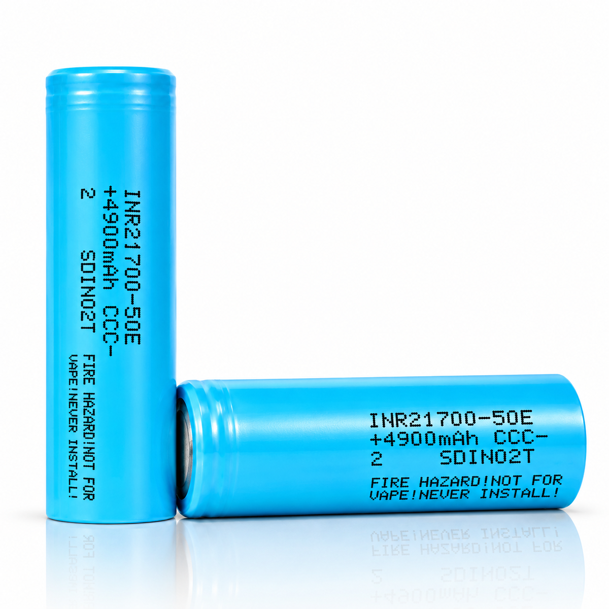
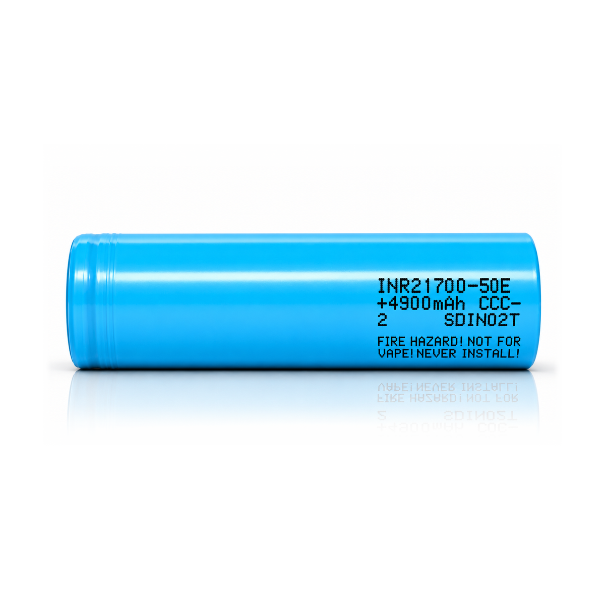
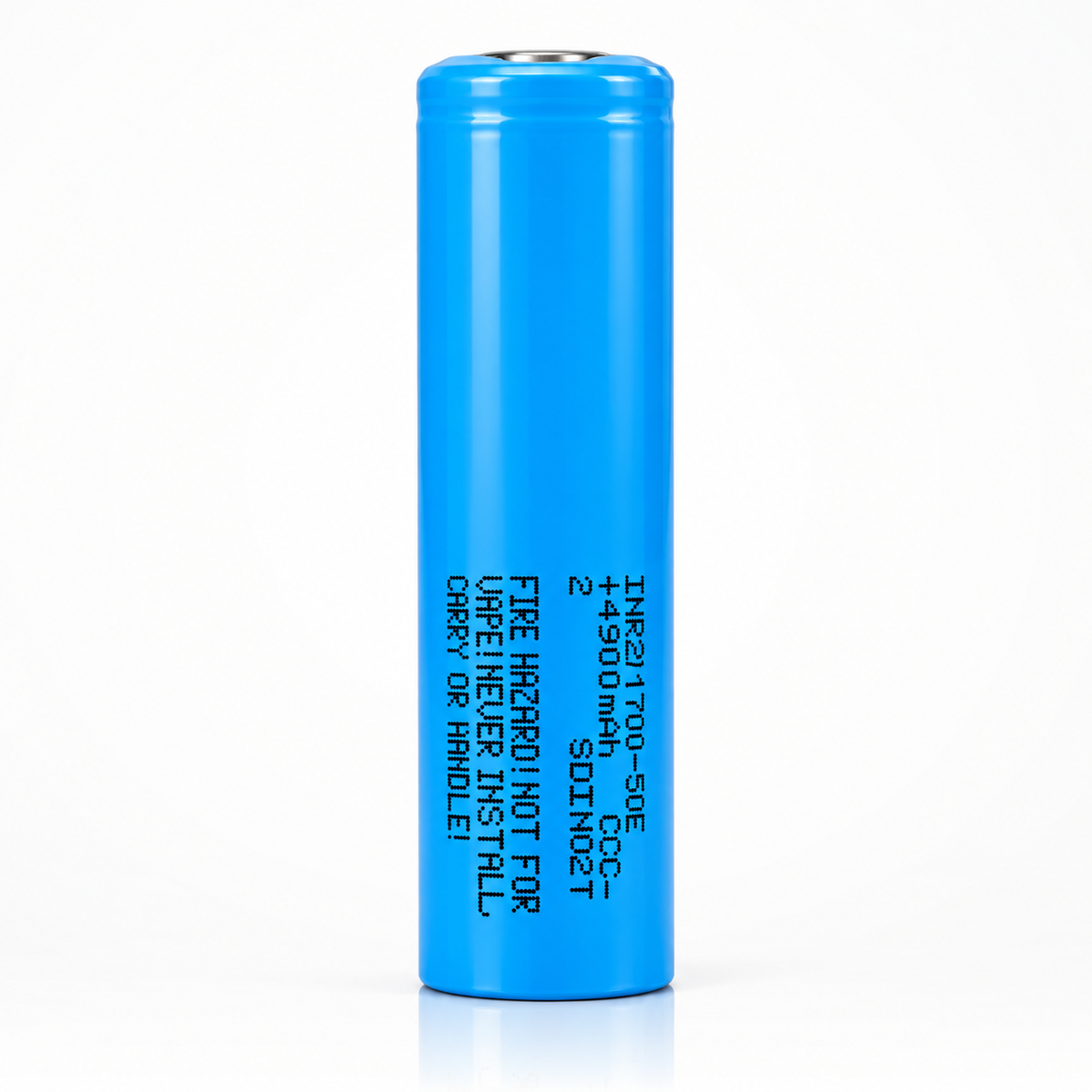
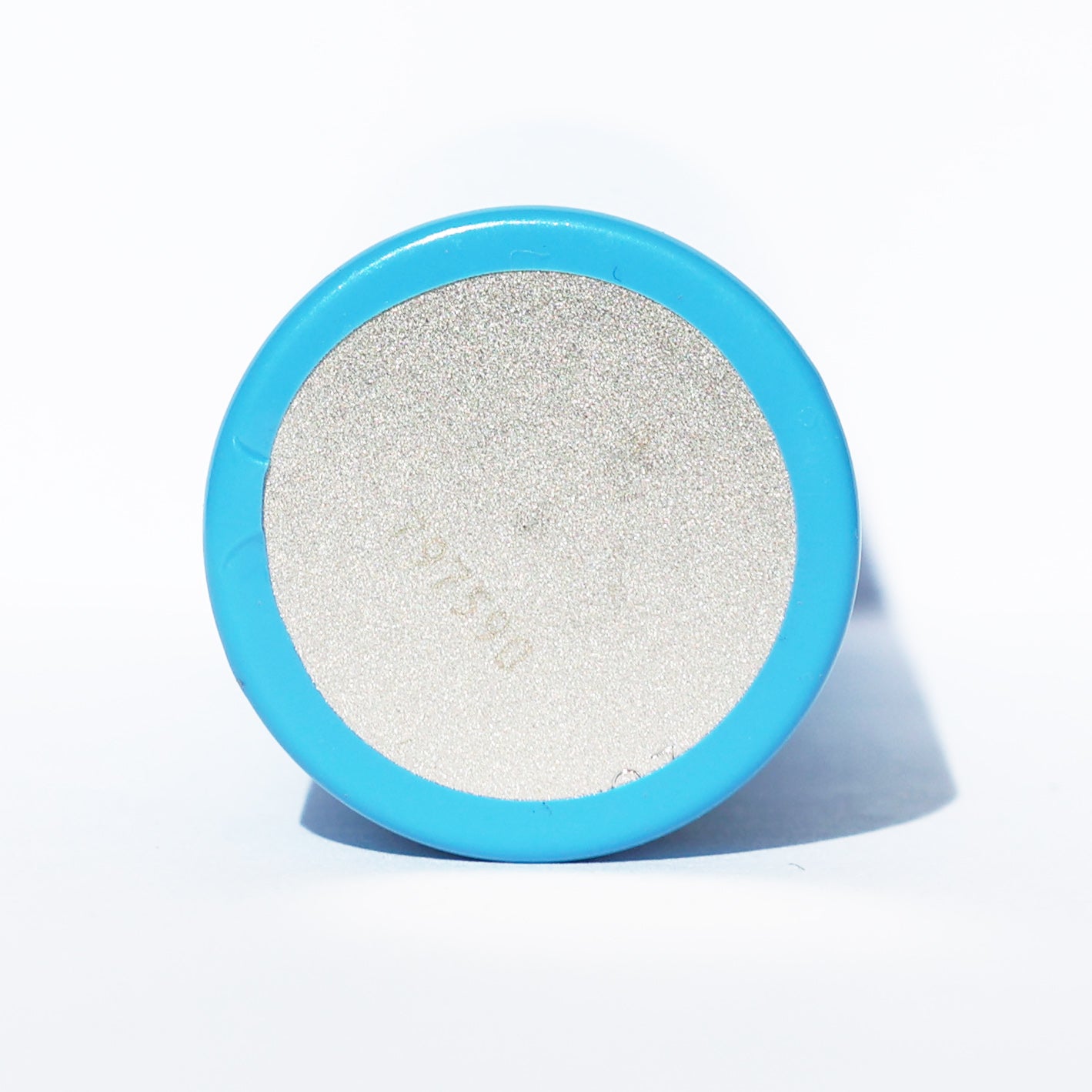


KEY SPECS · SAMSUNG SDI INR21700-50E
SOURCE [1]- SIZE
- Ø21.25 × 70.80 mm
- max. · with sleeve
- CAPACITY
- Not stated by manufacturer typ.
- 4,900 mAh min.
- 0.2C to 2.5 V, 23 °C
- CURRENT
- 9.8 A
- max. continuous
- condition not stated by manufacturer
- TEMPERATURE
- −20 to 60 °C
- discharge · ambient
- charge 0 to 45 °C · ambient
[1] Specification of Product, SDI Model INR21700-50E, Version No. V1.0, on file since 2025-12-08
SAMSUNG SDI · 21700 · INR21700-50E
A 21700 lithium-ion cell: 4,900 mAh standard minimum capacity at 0.2C, 4,753 mAh rated minimum at 1C, and 9.8 A maximum discharge current, printed “9,800mA (for continuous discharge)” [1]. Below: every rating with its condition, the figures Samsung prints in its tables and reports, and what we calculated from them, so you can check each number.
CAPACITY4,900 mAhminimum at 0.2C; 4,753 mAh minimum at 1C [1]
CONTINUOUS9.8 Amaximum “for continuous discharge”; no temperature condition printed [1]
MAX. CHARGE4.9 A“not for cycle life”; standard charge 2.45 A, CC-CV to 4.2 V, charging time 4 h [1]
ENERGY17.79 Whminimum: 3.63 V × 4,900 mAh [1]; 17.787 Wh rating in the SDS [3]
AC IMPEDANCE≤ 28 mΩinitial, AC 1 kHz, after standard charge [1]
MASS69.5 gmaximum [1]
A bare cell: a component for protected packs and devices built for it. Not for vaping. Charge on a lithium-ion (Li-ion) charger that stops at 4.2 V.
01SPEC PLATE
Every rating, with its condition.
Samsung’s data sheet for the 50E is titled Specification of Product [1]; this page calls it the specification. The newest we hold is Version No. V1.0, dated 2018-07-11. Its ratings come first, copied as printed. Then the capacity figures its tables print, our arithmetic, and facts from the safety data sheet (SDS) [3] and the UN38.3 transport test report [4]. Each row names its source or shows its formula.
| SPECIFICATION | VALUE | CONDITION · SOURCE |
|---|---|---|
| RATED · MANUFACTURER copied from specification [1] | ||
| MODEL CODE | INR21700-50E | Spec. No. and SDI Model, as printed [1] |
| CAPACITY, STANDARD | 4,900 mAh | minimum; 0.2C (980 mA) to 2.5 V after standard charge, at 23 °C [1] |
| CAPACITY, RATED | 4,753 mAh | minimum; 1C (4,900 mA) to 2.5 V after standard charge, at 23 °C; printed as 97 % of 4,900 mAh [1] |
| CAPACITY, TYPICAL | — | Not stated by manufacturer [1] |
| 1C | 4,900 mA | the current [1] defines as 1C |
| NOMINAL VOLTAGE | 3.63 V | [1] |
| CHARGE VOLTAGE | 4.2 V | charging method “CC-CV (constant voltage with limited current)” [1] |
| DISCHARGE CUT-OFF | 2.5 V | end of discharge [1] |
| STANDARD CHARGE | 2.45 A | 0.5C (2,450 mA), CC-CV to 4.2 V, 0.02C (98 mA) cut-off, at 23 °C; charging time 4 hours [1] |
| MAX. CHARGE CURRENT | 4.9 A | “4,900mA (not for cycle life)”; no charging time printed for it [1] |
| MAX. DISCHARGE CURRENT | 9.8 A | “9,800mA (for continuous discharge)”; no temperature or other condition printed with it; the non-continuous figure is left out [1] |
| CHARGE TEMPERATURE | 0 to 45 °C | ambient [1] |
| DISCHARGE TEMPERATURE | −20 to 60 °C | ambient; a pack’s discharge over-temperature protection “should not be over 70°C of Cell surface temperature” [1] |
| AC IMPEDANCE | ≤ 28 mΩ | initial internal impedance, AC 1 kHz, after standard charge [1] |
| CYCLE LIFE | ≥ 3,802 mAh | after 500 cycles: 2,450 mA charge to 4.2 V, 0.05C (245 mA) cut-off; 1C (4,900 mA) discharge to 2.5 V; room temperature; 80 % of the rated discharge capacity [1] |
| RECOVERY AFTER STORAGE | ≥ 4,410 mAh | 20 days at 60 °C from standard charge, then 0.2C (980 mA) to 2.50 V at 23 °C; 90 % of the standard discharge capacity [1] |
| RECOVERY 80 % AFTER STORAGE | −20 to 23 °C | for 1 year; −20 to 45 °C for 3 months; −20 to 60 °C for 1 month; kept at the ex-factory “30% of charge” [1] |
| STORAGE | 0 to 23 °C | humidity below 65 %; long-term at the shipping voltage; the pack guideline recommends 20 °C [1] |
| AS SHIPPED | 3.53–3.63 V | ex-factory voltage; 30 % of charge [1] |
| DIAMETER | 21.25 mm | maximum, “Top Diameter”, with sleeve [1] |
| HEIGHT | 70.80 mm | maximum, with sleeve [1] |
| MASS | 69.5 g | maximum [1] |
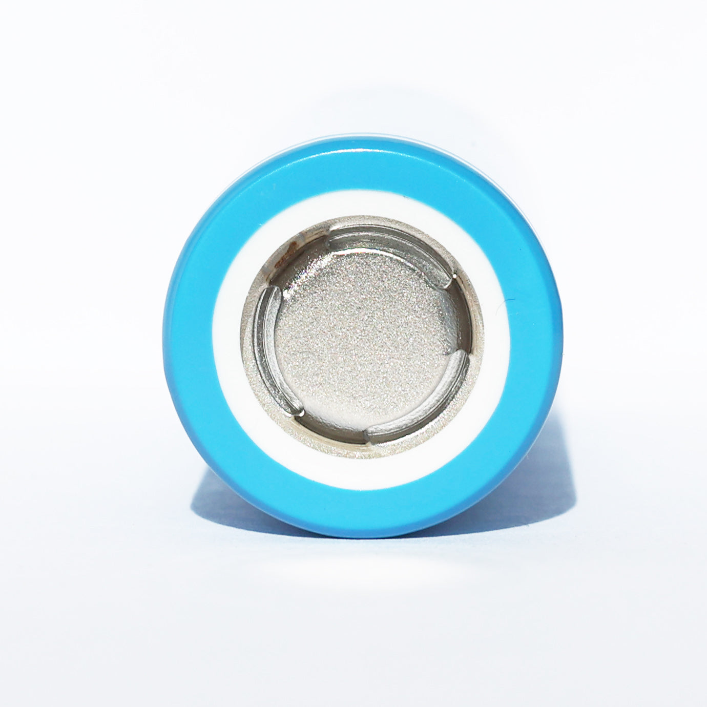
| TERMINAL · PROTECTION | Flat top · none | as sold: bare cell, no protection circuit; terminal style not stated in [1] |
| + Source: [1] Samsung SDI, Specification of Product, Spec. No. INR21700-50E, SDI Model INR21700-50E, Version No. V1.0 (“General Version” in its revision history), Date of Application 2018/07/11 (as printed); on file since 2025-12-08; not linked, because every page is headed “SAMSUNG SDI Confidential Proprietary” and watermarked with the name of the customer it was issued to. Call or text to ask about it | ||
| SPECIFICATION | VALUE | CONDITION · SOURCE |
|---|---|---|
| PRINTED IN THE SPECIFICATION’S TABLES percent of the 4,900 mAh standard discharge capacity, as printed; mAh calculated [1] | ||
| CAPACITY AT 2C (9.8 A) | 95 % | ≈ 4,655 mAh; to 2.50 V after standard charge at 23 °C; [1] §7.6 |
| CAPACITY AT 1C (4.9 A) | 97 % | ≈ 4,753 mAh, matching the 4,753 mAh rated minimum; [1] §7.6 |
| DISCHARGE AT −10 °C | 70 % | ≈ 3,430 mAh at 1C (4,900 mA), after standard charge at 23 °C; [1] §7.5 |
| DISCHARGE AT 40 °C | 97 % | ≈ 4,753 mAh at 1C; 23 °C also prints 97 %, because the table discharges at 1C; [1] §7.5 |
| CALCULATED arithmetic on [1], shown so you can check it | ||
| MAX. DISCHARGE AS C-RATE | 2C | 9,800 mA “for continuous discharge” ÷ 4,900 mA, the 1C in [1]; [1] §7.6 prints “2C (9,800mA)” |
| MAX. CHARGE AS C-RATE | 1C | 4,900 mA “not for cycle life” ÷ 4,900 mA [1] |
| RUNTIME AT 9.8 A | 28.5 min | 4,655 mAh ÷ 9.8 A, from [1] §7.6 |
| ENERGY, MINIMUM | 17.79 Wh | 3.63 V nominal × 4,900 mAh standard minimum [1]; 17.25 Wh with the 4,753 mAh rated minimum |
| VOLUME | 25.1 cm³ | π × (21.25 ÷ 2)² × 70.80 mm³, the maximum size [1] |
| FROM THE SAFETY DATA SHEET (SDS) AND UN38.3 TRANSPORT TEST REPORT copied as printed from [3] and [4] | ||
| CHEMISTRY | Li-ion | [1] says lithium-ion only; the SDS prints “Battery-System: Lithium-ion (Li-ion)” and describes the cathode as “based on lithiated metal oxide (Cobalt, Nickel)” [3] |
| ENERGY RATING | 17.787 Wh | “Wh rating: 17.787 Wh”, SDS [3]; “17.78Wh” in the UN38.3 report [4] |
| RATED CAPACITY, SDS | 4.90 Ah | “Rated Capacity: 4.90 Ah”, no condition printed [3]; “4900mAh” in [4]; not the same figure as [1]’s 4,753 mAh rated discharge capacity at 1C |
| TRANSPORT | UN3480 · Class 9 | “UN Number : 3480”, packing group II; UN3481 when packed with or contained in equipment [3] |
| UN38.3 | SDI-UN-200714-03 | Ver.03, issued 2020-07-14, test dates 2018-11-27 to 2018-12-29; T1–T6 and T8 PASS; T7 N/A, remark “Battery only” (a test for batteries, not cells); Samsung SDI is named as both lab and manufacturer; cited, not linked [4] |
| MASS · UN38.3 TEST CELLS | 69.011–69.283 g | the 10 cells weighed before T1 [4]; not our lot; maximum 69.5 g [1] |
| SAFETY DATA SHEET | Revision no.: 01 | dated 2020-01-01; section 16.1 prints “Date Updated : 28 June. 2018”; MODEL INR21700-50E [3] |
| STORAGE · SDS | ≈ 20 °C | “Storage at room temperature (approx. 20℃) at approx. 40% of the nominal capacity” [3] |
| + Source: [1] Samsung SDI, Specification of Product, Spec. No. INR21700-50E, SDI Model INR21700-50E, Version No. V1.0 (“General Version” in its revision history), Date of Application 2018/07/11 (as printed); on file since 2025-12-08; not linked, because every page is headed “SAMSUNG SDI Confidential Proprietary” and watermarked with the name of the customer it was issued to. Call or text to ask about it + Source: [3] Samsung SDI, Safety Data Sheet, MODEL INR21700-50E, Revision no.: 01, January 1st 2020 (its section 16.1 prints “Date Updated : 28 June. 2018”); prepared “In accordance with Regulation (EU) 2015/830 (REACH), Annex II, and OSHA 29 CFR 1910.1200”; its closing section XVI names other product codes (PA0001N0006A/PA0001N0007A/PA001N0008A), as printed, while its page headers and section 1.1 name the INR21700-50E; on file 2026-10-20 · SDS PDF + Source: [4] Samsung SDI, UN TEST REPORT, Test Summary, Model Name INR21700-50E, SDI-UN-200714-03 Ver.03, issued 2020.07.14; test dates 2018.11.27~2018.12.29; to the “Manual of Tests and Criteria, section 38.3 Sixth revised edition Amendment 1”; Samsung SDI Co., Ltd is named as both the testing laboratory and the manufacturer, Cheonan, Korea; on file 2026-10-20; quoted and cited here but not linked, because its first page carries a Samsung SDI notice, in Korean, that the information may not be printed, distributed or taken out without the permission of Samsung SDI’s information-asset manager (our translation). Call or text to ask about it | ||
RATED · [1]FIG 1.1
Voltage window
2.5 V3.63 V4.2 Vcut-offnominalcharge
Black marks: rated voltages [1]. Orange band: the voltage cells ship at, 3.53–3.63 V, 30 % of charge [1]; its top equals the 3.63 V nominal voltage.
RATED · [1]FIG 1.2
Current limits
Standard charge 2.45 A · 0.5C · CC-CV to 4.2 V · charging time 4 hours
2.45 A
Max. charge 4.9 A · 1C · “not for cycle life”
4.9 A
Max. discharge 9.8 A · 2C · “for continuous discharge”
9.8 A
Currents as rated in [1], each with its condition. C-rates against the 4,900 mA that [1] defines as 1C. Its cycle-life rating charges at the same 2,450 mA as the standard charge. [1] also prints a second discharge figure, “not for continuous discharge”, with no duration or pulse definition; a non-continuous figure is not a rating, so it is left out.
RATED · [1]FIG 1.3
Temperature envelope
Discharge, ambient −20 to 60 °C [1]
Charge, ambient 0 to 45 °C [1]
Discharge protection, cell surface a pack’s cut-off at no more than 70 °C, at the hottest cell [1]
Printed test points [1] §7.5: −10, 23 and 40 °C
Operating ranges as rated in [1], in °C, labeled ambient. Note (*2) of [1] adds that a pack’s discharge over-temperature protection “should not be over 70°C of Cell surface temperature”, set where the pack heats most. Last row: the temperatures of the capacity table in [1] §7.5, shown in section 04 below.
RATED · [1]FIG 1.4
Recovery 80 % after storage, by duration
For 1 month −20 to 60 °C
For 3 months −20 to 45 °C
For 1 year −20 to 23 °C
Storage time and temperature for which [1] specifies more than 80 % capacity recovery, with the cell kept as shipped, at 30 % of charge. Its handling section says to store cells at 0 to 23 °C, humidity below 65 % [1].
DOCUMENTS · [1][3][4]FIG 1.5
Capacity, as each document prints it
Rated, at 1C ≥ 4,753 mAh minimum at 4,900 mA [1]
4,753
Standard, at 0.2C ≥ 4,900 mAh minimum at 980 mA [1]
4,900
SDS “Rated Capacity: 4.90 Ah”, no condition [3]
4,900
UN38.3 report “4900mAh”, no condition [4]
4,900
Each document’s capacity figure, as printed, on a 4,700–4,950 mAh scale; the axis doesn’t start at zero. 4,900 mAh is a minimum at 0.2C in [1] and a figure with no condition in [3] and [4]; [1]’s minimum at 1C is 4,753 mAh. “Rated” means different figures: the SDS calls its 4.90 Ah “Rated Capacity”, while [1]’s rated discharge capacity is the 4,753 mAh minimum at 1C. [1] prints no typical or nominal capacity, and none of the four documents prints a higher capacity figure.
DOCUMENTS · [1][3][4]FIG 1.6
Energy, by document
Specification, calculated 3.63 V × 4,900 mAh standard minimum; [1] prints no Wh
17.79
Specification, calculated at 1C 3.63 V × 4,753 mAh rated minimum
17.25
SDS “Wh rating: 17.787 Wh” [3]
17.787
UN38.3 report “17.78Wh”, printed with “4900mAh” [4]
17.78
Wh as printed in [3] and [4], beside our arithmetic for the specification [1], which prints no Wh figure. The SDS’s 17.787 Wh equals 3.63 V × 4.90 Ah; [4] prints “17.78Wh”. Scale 17.0–18.0 Wh.
02 · CAPACITY
95 % of 4,900 mAh at 9.8 A.
The table in [1] §7.6 prints the 50E’s capacity at three currents, from 0.2C (980 mA) to 2C (9,800 mA), its maximum “for continuous discharge”, as a percent of the 4,900 mAh standard discharge capacity. At 9.8 A it prints 95 %: about 4,655 mAh, or about 28.5 minutes at 9.8 A by our arithmetic.
0.98 A · 0.2C4,900 mAhstandard minimum, 100 % [1]
9.8 A · 2C4,655 mAh95 % printed in [1]; mAh and 28.5 min calculated
CALCULATED FROM [1]FIG 2.1
mAh
4,6504,7004,7504,8004,8504,90002468104,9004,7534,655
Discharge current, A
Data: [1] §7.6, discharge rate · after standard charge at 23 °C, to 2.50 V · percent of 4,900 mAh, mAh calculated · the line joins the three printed points; Samsung prints no curve between them · 9.8 A is the maximum “for continuous discharge” · axis starts at 4,600 mAh · data table under fig 3.1
03BY CURRENT
Capacity and runtime, by current.
The table in [1] §7.6 prints the capacity at 0.2C, 1C and 2C (980, 4,900 and 9,800 mA) as a percent of the 4,900 mAh standard discharge capacity. The mAh and the runtime are arithmetic on those percents, with the formula under each.
CALCULATED FROM [1]FIG 3.1
Capacity delivered, by current
Capacity to 2.50 V at each current, after standard charge at 23 °C, printed in [1] §7.6 as a percent of the 4,900 mAh standard discharge capacity; mAh = percent × 4,900. The 1C row matches the ≥ 4,753 mAh rated capacity [1]. Orange: 9.8 A, the maximum “for continuous discharge” [1].
DATA TABLE · FIG 3.1
| CURRENT | C-RATE | PRINTED % | mAh | RUNTIME |
|---|---|---|---|---|
| 0.98 A | 0.2C | 100 | 4,900 | 5 h 00 min |
| 4.9 A | 1C | 97 | 4,753 | 58.2 min |
| 9.8 A | 2C | 95 | 4,655 | 28.5 min |
CALCULATED FROM [1]FIG 3.2
Runtime at a constant current
Runtime = capacity ÷ current, from the mAh in fig 3.1: one full standard charge, constant current to 2.50 V at 23 °C. A device whose average draw is below its peak current runs longer than the figure at that peak.
What 9.8 A means
- [1] prints the maximum discharge current as “9,800mA (for continuous discharge)”. It prints no temperature, cut-off or duration with it; its tests run at 23 ± 3 °C unless stated otherwise [1] §6.1.
- At 2C (9,800 mA), [1] §7.6 prints 95 % of the standard discharge capacity: about 4,655 mAh.
- Its handling section says the cell “shall be discharged continuously at less than maximum discharge current”, and that a higher current is to be discussed with Samsung SDI [1].
- Separately, Note (*2) of [1], attached to the operating-temperature rating, sets a pack’s discharge over-temperature protection at no more than 70 °C on the hottest cell surface. It is a pack protection setting, not a condition attached to the 9.8 A figure.
- [1] also prints a figure “not for continuous discharge”, with no duration or pulse definition. It is not a rating, so we leave it out.
04TEMPERATURE
Capacity in the cold and the heat.
One table in [1]: capacity when the discharge runs at −10, 23 and 40 °C, after a standard charge at 23 °C, all at 1C (4,900 mA). At −10 °C it prints 70 % of the standard discharge capacity. [1] prints no charge-temperature table.
CALCULATED FROM [1]FIG 4.1
Capacity, by discharge temperature
Capacity when the discharge runs at each temperature: 1C (4,900 mA) to 2.50 V after standard charge at 23 °C, with 3 h at the test temperature first where it differs from the 23 °C charge. Printed in [1] §7.5 as a percent of the standard discharge capacity, 4,900 mAh at 0.2C; because this table discharges at 1C, 23 °C reads 97 %, not 100 %. mAh calculated. −10 °C is the coldest point printed; the rated discharge range goes down to −20 °C.
DATA TABLE · FIG 4.1
| DISCHARGE °C | CHARGE °C | PRINTED % | mAh | RUNTIME AT 4.9 A |
|---|---|---|---|---|
| −10 °C | 23 °C | 70 | 3,430 | 42.0 min |
| 23 °C | 23 °C | 97 | 4,753 | 58.2 min |
| 40 °C | 23 °C | 97 | 4,753 | 58.2 min |
CALCULATED FROM [1]FIG 4.2
Runtime at 4.9 A, by temperature
Runtime = capacity ÷ 4.9 A, from fig 4.1: arithmetic on [1] §7.5. At −10 °C the same discharge ends after about 42.0 min, against 58.2 min at 23 °C.
What the table leaves out
- No capacity below −10 °C or above 40 °C, though discharge is rated at −20 to 60 °C ambient [1].
- No charge-temperature table: [1] rates charging at 0 to 45 °C ambient and prints no capacity after a cold or hot charge.
- [1] labels its operating temperatures ambient. The earlier tentative issue [2] printed the same numbers as cell surface temperature (section 08 below).
- In a pack, discharge over-temperature protection at no more than 70 °C on the hottest cell surface [1].
05CHARGING
Charging: 2.45 A standard, 4.9 A maximum.
The specification rates a 2,450 mA standard charge, CC-CV to 4.2 V, with a printed charging time of 4 hours, and a 4,900 mA maximum that is “not for cycle life” [1]. Its cycle-life rating charges at 2,450 mA. Charge between 0 and 45 °C ambient [1].
SPECS · [1][2]FIG 5.1
Charge time, as rated
Tentative issue [2], 2018-05-06V1.0 specification [1], 2018-07-11
Charging time as each specification prints it: “Standard charge: 3hours” in the tentative issue [2], “Standard charge : 4hours” in V1.0 [1], for the same 2,450 mA charge. Neither prints a time for the 4,900 mA maximum charge, or a charge curve. Values also in the section 08 table.
PACK GUIDELINE · [1]FIG 5.2
Voltage thresholds for a pack
Do not charge below 1.0 V · pack guideline [1]
Pre-charge 1.0–3.0 V at 0.1–0.5C · pack guideline [1]
Discharge cut-off 2.5 V cell rating; a pack’s cut-off “must be over 2.5V” [1]
Re-charge at least 0.1 V below the max. charging voltage · pack guideline [1]
Charge cut-off 4.2 V cell rating; the guideline prints “must be under 4.2V” [1]
Working range 2.5 to 4.2 V [1]
Voltage thresholds for a pack’s battery management system (BMS): the cell ratings in [1], and the pre-charge, re-charge and do-not-charge levels from the pack design guideline printed in [1]. The re-charge mark sits at 4.1 V, the highest the guideline allows. Below 1.0 V, the guideline says not to charge the cell at all.
SPECS · [1][2]FIG 5.3
Charge temperature
Charge, ambient 0 to 45 °C, [1] §3.16
Pack guideline “Charge temperature ranges : 0°C ~ 45°C” [1]
Tentative issue 0 to 45 °C, labeled “(Cell Surface Temperature)” [2]
Where charging is rated, in °C. V1.0 labels the range ambient [1]; the tentative issue [2] printed the same numbers as cell surface temperature. Orange: the V1.0 rating this page uses; black: the same range in the pack guideline [1]; gray: the tentative issue [2]. [1] prints no capacity table for charge temperature. Below 0 °C, don’t charge.
Before you charge
- Use a lithium-ion charger with a CC-CV profile that stops at 4.2 V.
- 2,450 mA is the standard charge, with a printed charging time of 4 hours [1]. 4,900 mA is the maximum [1] prints, marked “not for cycle life”, and its handling section says charging current “should be less than maximum charge current”. The cycle-life rating uses the 2,450 mA charge with a 245 mA cut-off.
- Charge between 0 and 45 °C ambient [1]. Below 0 °C, don’t charge.
- Don’t charge a cell that has fallen below 1.0 V; the pack guideline in [1] says not to.
- In a pack, a BMS (battery management system) should hold the charge cut-off below 4.2 V per cell (the pack guideline in [1] prints “Cut-off Voltage of charging must be under 4.2V.”), stop charging outside 0 to 45 °C, and stop a charge that isn’t complete within the specified time [1].
The values in fig 5.2 are printed as text in the pack design guideline of [1]; Samsung draws no chart of them. The guideline prints the charge cut-off as “must be under 4.2V” and the discharge cut-off as “must be over 2.5V”; the cell ratings are 4.2 V and 2.5 V [1]. In this section, figs 5.1 and 5.3 show the tentative issue [2] beside V1.0; section 08 below lists every changed figure.
06CYCLE LIFE AND STORAGE
What it keeps after use and storage.
[1] rates at least 3,802 mAh after 500 cycles, and at least 4,410 mAh after 20 days at 60 °C. It prints no cycle-life curve, so these are the two points on the page.
RATED · [1]FIG 6.1
Capacity after storage and cycling
Minimum capacity as rated in [1]. New at 0.2C and after 20 days at 60 °C: 980 mA to 2.50 V at 23 °C. New at 1C and after 500 cycles: 4,900 mA to 2.5 V; each cycle charges at 2,450 mA to 4.2 V with a 0.05C (245 mA) cut-off, at room temperature. A rating, not a warranty, and not a curve: [1] prints no capacity between cycle 1 and 500.
DOCUMENTS · [1][3]FIG 6.2
Storage charge, by document
As shipped 30 % of charge · 3.53–3.63 V [1]
30 %
SDS approx. 40 % of the nominal capacity, at approx. 20 °C [3]
40 %
State of charge for storage, as each document prints it. [1] says capacity recovers to more than 80 % after storage at the as-shipped charge (fig 1.4), and asks for long-term storage at the shipping voltage.
DOCUMENTS · [1][3]FIG 6.3
Storage temperature, by document
Handling section 0 to 23 °C, humidity below 65 % [1]
Pack guideline below 60 °C, 20 °C recommended [1]
SDS room temperature, approx. 20 °C [3]
Recovery 80 %, 1 year −20 to 23 °C [1]
Storage temperature as each document prints it; each includes about 20 °C. Orange: the handling section’s range, which this page follows; gray: the 1-year recovery range from fig 1.4. For 3 months or more, [1] says “It is strongly recommended that the Cell is preserved at dry and low-temperature.”
07TRANSPORT TESTS
What Samsung’s UN38.3 report records.
Samsung’s UN38.3 report [4] records PASS for T1–T6 and T8 on the INR21700-50E. T7, overcharge, is marked N/A with the remark “Battery only”: the UN38.3 overcharge test is for batteries, and this report covers the bare cell. Its tables also print what each cell did. Samsung SDI is named as both the testing laboratory and the manufacturer. The tests ran from 2018-11-27 to 2018-12-29, and the report was issued 2020-07-14, so it describes a manufacturer sample, not our lot. The report also records its packaging test, P1: a 1.2 m drop of a box of 130 cells, “Without release of contents”. We quote the report but don’t link it, because its first page carries a Samsung SDI notice restricting printing and distribution.
PRINTED IN [4]FIG 7.1
Highest temperature, by abuse test
T5 external short, first cycle 5 cells · fully charged · 96–112 °C
T5 external short, after 25 cycles 5 cells · fully charged · 92–114 °C
T6 impact, first cycle 5 cells · 50 % charge · 21–22 °C
T6 impact, 25th cycle 5 cells · 50 % charge · 21–22 °C
Pass limit, T5 and T6 external temperature not over 170 °C [4]
Highest external temperature of each cell, as printed in [4]: one tick per cell; the bar spans the lowest to the highest. T5 external short circuit: 10 fully charged cells, 5 at first cycle and 5 after 25 cycles (sample conditions A and B, which [4] prints for T1–T5); [4] prints no short-circuit resistance, temperature or duration. T6 impact (the report ticks impact, not crush): 10 cells at 50 % charge, 5 at first cycle and 5 at the 25th; no impact mass or drop height printed. T8 forced discharge: 20 fully discharged cells, 10 at first cycle and 10 after 25 cycles, initial current 4 A for 1 h, as printed. That is below the 9,800 mA maximum continuous discharge in [1]; [4] doesn’t say how the current was chosen. [4] prints no T8 temperatures, so T8 has no row. Pass criteria, condensed: T5 and T6, not over 170 °C, with no disassembly or fire (T5: or rupture) within 6 h; T8, no disassembly or fire within 7 days. [4] marks all 40 samples “O”: no disassembly and no fire, and in T5 no rupture.
DATA TABLE · FIG 7.1
| TEST | SAMPLE CONDITION, AS PRINTED | CELLS | MAX °C, EACH CELL | RANGE |
|---|---|---|---|---|
| T5 external short, first cycle | A: at first cycle, in fully charged states(5 pcs) | 5 | 103, 96, 105, 99, 112 | 96–112 °C |
| T5 external short, after 25 cycles | B: after 25th cycles ending in fully charged states(5 pcs) | 5 | 103, 95, 92, 106, 114 | 92–114 °C |
| T6 impact, first cycle | C: at first cycle, in 50% charged states(5 pcs) | 5 | 21, 22, 21, 22, 22 | 21–22 °C |
| T6 impact, 25th cycle | D: at 25th cycle, in 50% charged states(5 pcs) | 5 | 21, 21, 21, 22, 21 | 21–22 °C |
PRINTED IN [4]FIG 7.2
Voltage kept through T1–T4
Pass criterion residual voltage not less than 90% [4]
T1 altitude 99.98 % [4]
T2 thermal cycling 97.56–97.63 % [4]
T3 vibration 99.98–100.00 % [4]
T4 shock 100.00 % [4]
Open-circuit voltage after each test, as a percent of the voltage before it, printed in [4]: 10 cells, fully charged, 4.136–4.137 V before T1 and 4.035–4.036 V after T4. The same 10 cells ran T1 to T4: each test’s before-values are the previous test’s after-values in [4]. Where [4] prints a range, the mark shows its lower end. The scale starts at 85 %.
PRINTED IN [4]FIG 7.3
Mass of the cells in the report
g
68.969.169.369.51234567891069.5 g maximum [1][4]
Cell
Mass of the 10 cells weighed before T1, as printed in [4]: 69.011–69.283 g (mean 69.17 g, our arithmetic), against the 69.5 g maximum in [1] and [4]. Percent of weight loss after each of T1–T4: 0.00–0.02 %, as printed [4]; cells 1 and 7 weighed 0.001 and 0.002 g more after T2 than before it, printed as 0.00 %. The axis starts at 68.8 g. A 2018 manufacturer sample, not our lot.
DATA TABLE · FIG 7.3
| CELL | BEFORE T1 g | AFTER T1 | AFTER T2 | AFTER T3 | AFTER T4 |
|---|---|---|---|---|---|
| 1 | 69.283 | 69.280 | 69.281 | 69.277 | 69.277 |
| 2 | 69.126 | 69.126 | 69.115 | 69.115 | 69.115 |
| 3 | 69.221 | 69.221 | 69.213 | 69.213 | 69.213 |
| 4 | 69.169 | 69.165 | 69.162 | 69.162 | 69.162 |
| 5 | 69.185 | 69.182 | 69.177 | 69.173 | 69.169 |
| 6 | 69.253 | 69.253 | 69.251 | 69.251 | 69.251 |
| 7 | 69.065 | 69.065 | 69.067 | 69.062 | 69.062 |
| 8 | 69.169 | 69.166 | 69.163 | 69.163 | 69.163 |
| 9 | 69.238 | 69.238 | 69.233 | 69.228 | 69.221 |
| 10 | 69.011 | 69.011 | 69.010 | 69.010 | 69.010 |
Safety tests the specification lists
| TEST | METHOD, CONDENSED FROM [1] | CRITERIA | STANDARD NAMED | SECTION |
|---|---|---|---|---|
| Drop | Fully standard-charged cells dropped onto a concrete floor from 1.0 m, 3 times, in random orientations; at least 1 h of rest, then a visual inspection | No fire, no explosion. | IEC62133 | [1] §8.1 |
| Vibration | Per UN38.3, for each axis (X and Y for cylindrical cells): 7 Hz → 200 Hz → 7 Hz in 15 min, repeated 12 times, 3 h in total; 1 g from 7 to 18 Hz, and 8 g (amplitude 1.6 mm) to 200 Hz | No leakage, with less than 10% of OCV drop | UN38.3 | [1] §8.2 |
| Overcharge | Fully discharged cell charged at 4.6 V and 3C (14.7 A), at 23 °C, for 7 h | No fire, and no explosion. | UL1642 | [1] §9.1 |
| External short-circuit | Fully standard-charged cell shorted through an 80 ± 20 mΩ load until fire or explosion, or until it is below 0.2 V and its case is back within ± 10 °C of ambient; run at 20 ± 5 °C and at 55 ± 5 °C | No fire, and no explosion. | UL1642 | [1] §9.2 |
| Forced discharge | Discharged cell reverse-charged at 1.0C (4,900 mA) for 90 min | No fire, and no explosion. | IEC62133 | [1] §9.3 |
| Heating | Standard-charged cell heated at 5 °C per minute to 130 °C, then held 30 min in an oven | No fire, and no explosion. | UL1642 (10 min) and GB31241 (30 min) | [1] §9.4 |
Methods condensed in our words from sections 8 and 9 of [1]; criteria as printed, with the standard each names. [1] lists these as tests the cell is specified to meet and prints no results. Their voltages and currents, such as 4.6 V and 3C in the overcharge test, are abuse conditions, not ratings. The UN38.3 results above are a different set of tests, from [4].
08WHAT CHANGED
The tentative issue and V1.0, side by side.
[2] is a 4-page specification marked Tentative, dated 2018-05-06, with blank signature blocks. [1]’s revision history lists one earlier version, v0.0 of 2017-10-13, “First version (Tentative)”, and no 2018-05-06 issue; neither document says whether [2] is that version. Some listings still quote [2]’s figures. In short, V1.0 prints a 3.63 V nominal voltage (was 3.6 V), a 69.5 g maximum mass (was 69 g) and a 4-hour standard charging time (was 3 hours) for the same 2,450 mA charge. Its diameter entry reads 21.25 mm, the figure [2]’s own drawing already printed; [2]’s table said 20.25 mm. It changes the recovery-after-storage test to 20 days instead of 30, discharged at 0.2C instead of 1C, so its 4,410 mAh doesn’t compare directly with [2]’s 4,278 mAh. It labels the operating temperatures ambient instead of cell surface, with the same values, and raises the discharge over-temperature limit from 60 to 70 °C. [1] doesn’t say why these changed, or whether anything changed inside the cell. Every rating on this page follows [1].
| ITEM | TENTATIVE, 2018-05-06 [2] | V1.0, 2018-07-11 [1] |
|---|---|---|
| Nominal voltage, §3.4 | “3.6V” | “3.63V” |
| Charging time, §3.7 | “Standard charge: 3hours” | “Standard charge : 4hours” |
| Recovery after storage: capacity, §3.13 | “Capacity recovery (after the storage) ≥ 4,278mAh” | “Capacity recovery (after the storage) ≥ 4,410mAh” |
| Recovery after storage: basis, §3.13 | “(90% of the Rated Discharge Capacity @ RT)” | “(90% of the Standard discharge capacity @ RT)” |
| Recovery after storage: storage, §3.13 | “- Storage : 30 days @ 60’C” | “- Storage : 20 days @ 60’C” |
| Recovery after storage: discharge, §3.13 | “- Discharge : 1.0C(4,900mA) 2.50V cut-off @ RT” | “- Discharge : 0.2C(980mA) 2.50V cut-off @ RT” |
| Cell weight, §3.14 | “69g max” | “69.5g max” |
| Diameter, §3.15 | “Diameter : Φ Max.20.25mm”; its own Fig. 1 prints “Max. 21.25” | “Top Diameter : Φ Max.21.25mm” |
| Operating temperature basis, §3.16 | “(Cell Surface Temperature)”; charge 0 to 45 °C, discharge −20 to 60 °C | “(Ambient)”; the same values |
| Discharge over-temperature protection, Note (*2) | “should not be over 60’C of the cell surface temperature” | “should not be over 70°C of Cell surface temperature” |
| Contents | §1 to §4 (Fig. 1) only; 4 pages | adds §5 to §12 (impedance, capacity tables, safety tests, warranty, packaging) and the handling and pack design appendices; 20 pages |
Text in quotation marks is copied as printed in [2] and [1], with their own symbols; the rest is our summary. Wording-only differences are left out; the storage table keeps its values, though its title changes from “Storage Temperature” to “Recovery 80% after storage”. Unchanged between them: 4,900 mAh standard and 4,753 mAh rated minimums, 1C = 4,900 mA, 4.2 V charge, the 2,450 mA standard and 4,900 mA maximum charge currents, the 9,800 mA maximum “for continuous discharge”, 2.5 V cut-off, ≥ 3,802 mAh after 500 cycles, 70.80 mm maximum height, the operating and storage temperature values, and 30 % of charge ex-factory.
09COMPARE
Where the 50E sits.
Twelve other 21700 cells, each from its own data sheet. The 50E’s 9.8 A is the shortest discharge bar in the chart. Two sheets print a higher minimum capacity, and both also print a higher discharge figure: the Molicel M65A (6,400 mAh, 25.6 A; preliminary R&D data) and the Samsung 58E (5,330 mAh; its 10.66 A is our arithmetic from 2C). The Samsung 50G prints the same 4,900 mAh minimum. The conditions behind each figure differ, so the table quotes each sheet’s wording.
DATA SHEETS · [1][5]FIG 9.1
Minimum capacity and discharge, side by side
- Molicel P50B INR-21700-P50B4,850 mAh minimum · 5,000 typical60 A continuous · 80 °C cut-off
- Samsung 45T CC4503F1014,400 mAh minimum · 4,500 typical50 A continuous · 80 °C temp. cut; 35 A without
- Molicel P45B INR-21700-P45B4,350 mAh minimum · 4,500 typical45 A max. continuous · no condition printed
- Samsung 40T INR21700-40T4,000 mAh minimum · no typical printed45 A continuous · 80 °C temp. cut; 35 A without
- Molicel P42A INR-21700-P42A4,000 mAh minimum · 4,200 typical45 A continuous · no condition printed
- Samsung 50S INR21700-50SMinimum not stated by manufacturer · 5,000 typical45 A continuous · 80 °C temp. cut; 25 A without
- Sony/Murata VTC6A US21700VTC6A4,000 mAh minimum · 4,160 nominal40 A continuous max. · 80 °C temp. cut
- Molicel M65A 21700-M65A6,400 mAh minimum · 6,500 ± 70 mAh at 0.2C, no typical or nominal label printed25.6 A rating type not printed · 90 °C cut-off; preliminary
- Molicel M50A INR-21700-M50A4,800 mAh minimum · 5,000 typical15 A continuous · no condition printed
- Samsung 50G INR21700-50G (Ver. B)4,900 mAh minimum · no typical printed14.7 A for continuous discharge · −20 to 30 °C; 9.8 A at 31 to 60 °C
- LG M50LT INR21700M50LTMinimum not stated by manufacturer · no mAh capacity printed; “1C = 4800mA”14.4 A max. · 10 to 25 °C; 7.2 A at 25 to 55 °C, 2.4 A at −20 to 10 °C
- Samsung 58E CC5493F101 (Ver. A)5,330 mAh minimum · no typical printed10.66 A 2C for continuous discharge · 10.66 A = 2 × 5,330 mA, our arithmetic
- Samsung 50E INR21700-50E4,900 mAh minimum · no typical printed9.8 A for continuous discharge · no condition printed
Each cell’s figures copied from its own data sheet [1][5]. Bars start at zero: minimum capacity on a 0–7,000 mAh scale, discharge on 0–60 A. The condition sits beside each current; where a sheet prints two continuous figures, the bar shows the higher and the note gives the other. The 50E’s 4,900 mAh is its 0.2C standard minimum; its 1C rated minimum is 4,753 mAh [1]. Pulse and other non-continuous figures are left out.
| CELL | TYPICAL OR NOMINAL mAh | MINIMUM mAh | DISCHARGE AS PRINTED | CHARGE RATING AS PRINTED | MASS g |
|---|---|---|---|---|---|
|
Molicel P50B INR-21700-P50B |
5,000 typical | 4,850 | “Discharge Current, Continuous: 60 A (80°C cut-off)” | “Charge Current, Maximum: 25 A (70°C cut-off)” | 71 max |
|
Samsung 45T CC4503F101 |
4,500 typical | 4,400 | “Max. continuous discharge (Surface temperature): 35A(Without temperature cut) / 50A(With 80℃ temperature cut)” | “Max. charge current: 9A (for step charge) / 6A (continuous charge)” | 72 max |
|
Molicel P45B INR-21700-P45B |
4,500 typical | 4,350 | “Maximum continuous discharging current: 45A” (no condition printed; remark: “Cycle life is reduced at high rates.”) | “Maximum continuous charging current: 9A” (remark: “High rate charge cycle will decay fast.”) | 70 max |
|
Samsung 40T INR21700-40T |
not printed | 4,000 | “Max. continuous discharge (Surface temperature): 35A(Without temperature cut) / 45A(With 80℃ temperature cut)” | “Rated charge: CCCV, 6A, 4.20 V, 100mA cut-off” (this spec prints no separate max. charge current item) | 70 max |
|
Molicel P42A INR-21700-P42A |
4,200 typical | 4,000 | “Discharge Current, Continuous: 45 A” (no condition printed) | not printed on the Version 1.7 sheet (“Charge Current, Standard: 4.2 A”); Doc # INR21700P42A-01 Rev. 0.2: “Maximum charging current: 8.4A” | 70 max |
|
Samsung 50S INR21700-50S |
5,000 typical | Not stated by manufacturer | “Max. continuous discharge (Surface temperature): 25A(Without temperature cut) / 45A(With 80℃ temperature cut)” | “Max. charge current: 6A (continuous charge)” | 72 max |
| Sony/Murata VTC6A US21700VTC6A |
4,160 nominal | 4,000 | “Continuous Maximum Discharging Current: 40A (With 80deg.C temperature cut)” | “Maximum Charging Current: 6A (Continuous)” | not printed placeholder “xx ±1.5g” |
| Molicel M65A 21700-M65A |
6,500 ± 70 at 0.2C; no typical or nominal label printed | 6,400 | “Discharge current: 25.6A (90℃cut-off)” (the word continuous is not printed; preliminary R&D data) | “Charge current: 6.5A (Standard) / 6.5A (Max)” | 72.5 ± 1.5, as printed |
| Molicel M50A INR-21700-M50A |
5,000 typical | 4,800 | “Discharge Current, Continuous: 15 A” (no condition printed) | not printed on the V3 sheet (“Charge Current, Standard: 2.5 A”); Doc # INR21700M50A-01 Rev. 0.1: “Maximum charging current: 5.0A” | 70 max |
| Samsung 50G INR21700-50G (Ver. B) |
not printed | 4,900 | “Max. Discharge Current (*²): 3C (14,700mA, for continuous discharge @ -20℃~30℃) / 2C (9,800mA, for continuous discharge @ 31℃~60℃)” | “Max. Charge Current: 4,900mA (not for cycle life)” | 71 max |
| LG M50LT INR21700M50LT |
not printed “1C = 4800mA” | Not stated by manufacturer | “Max. Discharge Current (complete full charge)²⁾: -20 ~ 10℃ 0.5C (2,400mA) / 10 ~ 25℃ 3.0C(14,400mA) / 25 ~ 55℃ 1.5C(7,200mA)” (the sheet’s note 2 calls these the maximum continuous currents) | “Max. Charge Current (complete full charge)²⁾: 0 ~ 25℃ 0.3C (1,440mA) / 25 ~ 45℃ 0.7C (3,360mA)” | 68.2 ± 1.0, with tube and washer |
|
Samsung 58E CC5493F101 (Ver. A) |
not printed | 5,330 | “Max. Discharge Current (*²): 2C (for continuous discharge)” (the sheet prints 1C = 5,330 mA, so 10.66 A is our arithmetic; non-continuous figure not shown) | “Max. Charge Current: 1C (not for cycle life)” (1C = 5,330 mA as printed) | 74 max |
| Samsung 50E INR21700-50E |
not printed | 4,900 | “Max. Discharge Current: 9,800mA (for continuous discharge)” (non-continuous figure not shown) | “Max. Charge Current: 4,900mA (not for cycle life)” | 69.5 max |
Text in quotation marks is copied as printed from each manufacturer data sheet [1][5], newest version in our library, checked by a second reading; notes in parentheses are ours. Several of these sheets are marked draft, tentative or preliminary; Sources gives each version as printed. Links go to the bare-cell listing in our store.
10PACK MATH
From one cell to a pack.
How the single-cell ratings scale in series (S) and parallel (P). Illustrative arithmetic, not a pack rating.
V MAX4.2 × S
charge voltage, 4.2 V [1]
V NOMINAL3.63 × S
nominal voltage, 3.63 V [1]
CAPACITY4.9 × P
Ah, standard minimum at 0.2C; 4.753 × P at 1C [1]
CONTINUOUS9.8 × P
A: the 9,800 mA maximum “for continuous discharge” [1], times P*
| CONFIG | CELLS | V MAX | V NOMINAL | Ah MINIMUM | Wh MINIMUM | CONTINUOUS A* | CELL MASS g, MAX |
|---|---|---|---|---|---|---|---|
| 1S1P | 1 | 4.2 | 3.63 | 4.90 | 17.8 | 9.8 | 69.5 |
| 2S1P | 2 | 8.4 | 7.26 | 4.90 | 35.6 | 9.8 | 139.0 |
| 3S1P | 3 | 12.6 | 10.89 | 4.90 | 53.4 | 9.8 | 208.5 |
| 4S1P | 4 | 16.8 | 14.52 | 4.90 | 71.1 | 9.8 | 278.0 |
| 2S2P | 4 | 8.4 | 7.26 | 9.80 | 71.1 | 19.6 | 278.0 |
| 3S2P | 6 | 12.6 | 10.89 | 9.80 | 106.7 | 19.6 | 417.0 |
| 4S2P | 8 | 16.8 | 14.52 | 9.80 | 142.3 | 19.6 | 556.0 |
| 7S3P | 21 | 29.4 | 25.41 | 14.70 | 373.5 | 29.4 | 1,459.5 |
| 10S3P | 30 | 42.0 | 36.30 | 14.70 | 533.6 | 29.4 | 2,085.0 |
| 10S4P | 40 | 42.0 | 36.30 | 19.60 | 711.5 | 39.2 | 2,780.0 |
| 13S4P | 52 | 54.6 | 47.19 | 19.60 | 924.9 | 39.2 | 3,614.0 |
| 14S5P | 70 | 58.8 | 50.82 | 24.50 | 1,245.1 | 49.0 | 4,865.0 |
CALCULATED FROM [1]FIG 10.1
Continuous current ceiling, by parallel count
9.8 A × P: the single-cell maximum “for continuous discharge” [1] times the parallel count. A ceiling before derating, not a pack rating.
* 9.8 A × P multiplies the single-cell figure, “9,800mA (for continuous discharge)” with no temperature condition printed [1], by the number of cells in parallel. [1]’s handling section asks for continuous discharge at less than that maximum, so treat each figure as a ceiling, not a working current. Wh = 3.63 V × 4.9 Ah × S × P, from the minimum standard capacity. [1] rates discharge between −20 and 60 °C ambient and sets the pack’s discharge over-temperature protection at no more than 70 °C on the hottest cell surface: derate for heat, size the BMS, fusing and interconnects for the derated current, and use matched cells of one model and lot. Samsung’s pack guideline in [1] also asks for a second protective device, such as a PTC or PCM, more than 1 mm between cells, a pack current under 10 µA in sleep mode, and, for all seven applications it lists, partitions between the BMS and the cells and a “non-flammable (VO level) case”. Mass counts cells only. The UN38.3 report [4] is Samsung’s report on the bare cell, not on your pack; a pack you build needs its own UN38.3 testing before it ships as UN3480.
11SIZE AND FIT
Ø21.25 × 70.80 mm, flat top.
Drawn at its printed maximums, with sleeve, beside nominal 18650 and 21700 outlines at one scale. Check tight holders against the 70.80 mm maximum length and the 21.25 mm maximum diameter.
RATED · [1]FIG 11.1
Drawn to scale
All outlines drawn to the same scale. The 50E at its maximums with sleeve [1]; the other outlines are nominal format sizes, for scale only.
| DIMENSION | VALUE | CONDITION |
|---|---|---|
| Diameter | 21.25 mm | maximum, “Top Diameter”, with sleeve [1] |
| Height | 70.80 mm | maximum, with sleeve [1] |
| Mass | 69.5 g | maximum [1]; 69.01–69.28 g for the 10 cells weighed in [4] |
| Terminal | Flat top | as sold, bare cell; not stated in [1] |
| Volume | 25.1 cm³ | π × (21.25 ÷ 2)² × 70.80 mm³, the maximum |
Check that your holder or device takes a flat-top 21700 cell 70.80 mm long and 21.25 mm across (maximums) [1]. Spot-weld nickel strip for packs; don’t solder to the cell.
12USE IT RIGHT
Keep it inside its ratings.
What this cell is, and how to use it within its ratings.
- This is a bare cell: a component for protected packs and devices built for it. It is not a standalone consumer battery and not for vaping.
- Flat top, unprotected. Check that your device takes a flat-top cell 70.80 mm long and 21.25 mm across (maximums) [1].
- Charge on a lithium-ion (Li-ion) charger that stops at 4.2 V. End discharge at 2.5 V [1].
- Stay inside the ratings [1]: discharge continuously at less than 9.8 A, the maximum “for continuous discharge”, between −20 and 60 °C ambient; charge at 2.45 A standard and below the 4.9 A maximum (“not for cycle life”), between 0 and 45 °C ambient.
- Don’t leave, charge or use cells where it may get hotter than 60 °C, such as a closed car. Don’t heat a cell, take it apart or burn it [1].
- Keep cells away from children [1]. Replace a torn wrap before use. Carry cells in a case, never loose.
- For packs: matched cells of one model and lot, a BMS, a second protective device, fusing, and a way for heat to leave.
Questions? Call 1-800-547-3050 or text 1-833-419-2192 to ask a person.
Documents
The SDS [3] is linked, unaltered, as posted on our store. The specifications [1] and [2] and the UN38.3 report [4] are on file but not linked. Every page of [1] and [2] is headed “SAMSUNG SDI Confidential Proprietary” and watermarked with the name of the customer it was issued to. The first page of [4] carries a Samsung SDI notice, in Korean, that the information may not be printed, distributed or taken out without permission. This page quotes and cites all four; versions are listed as printed. Call or text to ask about them.
Ships from Stockbridge, GA. Most in-stock orders ship within 1 business day.
13QUESTIONS
Questions, answered.
Short answers. Where an answer comes from a document, it carries its source; the rest is standard handling practice. Anything else: call 1-800-547-3050 or text 1-833-419-2192.
Is the 50E a protected cell?
No. It is a bare flat-top cell with no protection circuit. Use it only in packs with a battery management system (BMS) or in devices built for unprotected cells.
What capacity does Samsung rate it at?
4,900 mAh minimum at 0.2C (980 mA), which [1] calls the standard discharge capacity, and 4,753 mAh minimum at 1C (4,900 mA), which it calls the rated discharge capacity; both to 2.5 V after a standard charge at 23 °C [1]. “Rated” means a different figure in the SDS: it prints “Rated Capacity: 4.90 Ah” [3], and the UN38.3 report prints “4900mAh” [4], both with no condition. [1] prints no typical or nominal capacity, and none of these documents prints a capacity above 4,900 mAh.
What does “9,800mA (for continuous discharge)” mean?
It is the maximum current [1] rates for continuous discharge, as distinct from the separate figure it marks “not for continuous discharge”. [1] prints no temperature cut-off or other condition with it; its tests run at 23 ± 3 °C unless stated otherwise [1] §6.1, and discharge is rated at −20 to 60 °C ambient. Its rate table discharges at 9,800 mA to 2.50 V after a standard charge at 23 °C and prints 95 % of the standard discharge capacity, about 4,655 mAh [1] §7.6. [1]’s handling section asks for continuous discharge at less than the maximum, so plan each cell in a pack for less than 9.8 A. This page has no 9.8 A data from our own lot.
Why do some listings quote a higher current?
The specification also prints a discharge figure marked “not for continuous discharge”, with no duration or pulse definition, and some listings repeat it as if it were a rating. We don’t list it. 9.8 A, the maximum “for continuous discharge” [1], is the discharge figure we publish.
Why do other listings show different figures?
Some come from Samsung’s earlier tentative specification [2], dated 2018-05-06, which printed 3.6 V nominal, 69 g maximum, a 20.25 mm diameter (its own drawing says 21.25 mm) and a 3-hour standard charging time; every changed figure is listed in section 08 above. This page follows the V1.0 specification [1]: 3.63 V nominal, 69.5 g maximum, 21.25 mm maximum diameter and a 4-hour charging time.
How fast can I charge it?
The standard charge is 2,450 mA (0.5C), CC-CV to 4.2 V with a 98 mA cut-off; [1] prints a charging time of 4 hours for it. The maximum is 4,900 mA (1C), marked “not for cycle life”: the 500-cycle rating in [1] charges at 2,450 mA, so it doesn’t cover charging at 4,900 mA. [1] prints no charging time for the maximum, and its handling section says charging current “should be less than maximum charge current”. Charge between 0 and 45 °C ambient [1].
What charger should I use?
A lithium-ion charger with a CC-CV profile (constant current, then constant voltage) that stops at 4.2 V. Not a NiMH, LiFePO4 or lead-acid charger.
How long will it run at my current?
Runtime ≈ capacity ÷ current. Calculated from the capacities in [1] §7.6, after a full standard charge at 23 °C: about 5 h 00 min at 0.98 A, 58.2 min at 4.9 A and 28.5 min at 9.8 A (fig 3.2). For your own draw, divide 4,900 mAh by your current in mA to get hours, and expect a little less at higher currents (fig 3.1).
How does cold affect it?
At −10 °C, the coldest point in its temperature table, [1] §7.5 prints 70 % of the 4,900 mAh standard discharge capacity at 1C, about 3,430 mAh, against 97 % at 23 °C. Discharge is rated down to −20 °C ambient, but [1] prints no capacity below −10 °C, and no charge-temperature table. Don’t charge below 0 °C.
How many cycles will it last?
The specification rates at least 3,802 mAh, 80 % of the rated discharge capacity, after 500 cycles of 2,450 mA charge (245 mA cut-off) and 4,900 mA discharge to 2.5 V at room temperature [1]. It gives no figure for other currents or temperatures, and no end-of-life count. Heat, current, depth of discharge and storage all change the result.
What chemistry is it?
Lithium-ion; the specification says no more than that [1]. The posted SDS describes the anode as “based on intercalation graphite” and the cathode as “based on lithiated metal oxide (Cobalt, Nickel)”, and lists lithium nickel oxide at 25–35 % and cobalt lithium dioxide at 1–5 % by weight [3]. An older SDS on file (Revision no.: 02, dated 2018-03-13, not posted) describes the anode as “based on intercalation graphite & silicon” and the cathode as “based on lithiated metal oxide (Cobalt, Nickel, Aluminium)”. Samsung doesn’t say why the editions differ; this page follows the newer, posted SDS [3].
Can I use it in a vape or e-cigarette?
No. It is a bare cell: a component for protected packs and devices built for it, not for vaping. The specification [1] has no clause on vaping; the wrap of the sample cell photographed in Samsung’s UN38.3 report reads “NOT FOR VAPE!” [4].
Can I solder to it?
Don’t solder directly to the cell: Samsung’s handling precautions say “Don't solder on the battery directly” [1], and its pack guideline warns that soldering heat may damage components “such as separator and insulator” [1]. Spot-weld nickel strip, or use a holder.
Can I mix 50E cells with other cells?
No, not in the same pack. [1] says not to mix cell types or makers, or cells from different batches, and not to use old and new cells together. Use cells of one model and lot, at the same state of charge. In series, the weakest cell reaches 2.5 V first and limits the whole pack.
How should I store spare cells?
In a case, away from metal objects, somewhere dry. [1]’s handling section says to store cells at 0 to 23 °C, humidity below 65 %, and its pack guideline recommends 20 °C. For long-term storage it asks for the shipping voltage, 3.53–3.63 V, 30 % of charge [1]. The SDS suggests room temperature, approx. 20 °C, at approx. 40 % [3]; this page follows the specification. Check the voltage every few months.
How does it ship?
As UN3480, “LITHIUM ION BATTERIES”, Class 9, packing group II, under the SDS [3]; UN3481 when packed with or contained in equipment. Samsung’s UN38.3 report [4] covers the INR21700-50E bare cell; the tests ran from 2018-11-27 to 2018-12-29, and the report was issued 2020-07-14. A pack built from these cells needs its own UN38.3 testing.
14SOURCES
Sources and method.
Where every number on this page comes from.
- + Source: [1] Samsung SDI, Specification of Product, Spec. No. INR21700-50E, SDI Model INR21700-50E, Version No. V1.0 (“General Version” in its revision history), Date of Application 2018/07/11 (as printed); on file since 2025-12-08; not linked, because every page is headed “SAMSUNG SDI Confidential Proprietary” and watermarked with the name of the customer it was issued to. Call or text to ask about it
- + Source: [2] Samsung SDI, Specification of Product, Spec. No. INR21700-50E, Version No. Tentative, Date of Application 2018/ 05 / 06 (as printed), issued to a different customer, with blank signature blocks; [1]’s revision history lists only v0.0 ‘17-10-13 “First version (Tentative)” before V1.0, and we can’t tell whether [2] is that version; on file, not linked, because it is also headed “SAMSUNG SDI Confidential Proprietary” and watermarked with its customer’s name; used on this page only to show what changed
- + Source: [3] Samsung SDI, Safety Data Sheet, MODEL INR21700-50E, Revision no.: 01, January 1st 2020 (its section 16.1 prints “Date Updated : 28 June. 2018”); prepared “In accordance with Regulation (EU) 2015/830 (REACH), Annex II, and OSHA 29 CFR 1910.1200”; its closing section XVI names other product codes (PA0001N0006A/PA0001N0007A/PA001N0008A), as printed, while its page headers and section 1.1 name the INR21700-50E; on file 2026-10-20 · SDS PDF
- + Source: [4] Samsung SDI, UN TEST REPORT, Test Summary, Model Name INR21700-50E, SDI-UN-200714-03 Ver.03, issued 2020.07.14; test dates 2018.11.27~2018.12.29; to the “Manual of Tests and Criteria, section 38.3 Sixth revised edition Amendment 1”; Samsung SDI Co., Ltd is named as both the testing laboratory and the manufacturer, Cheonan, Korea; on file 2026-10-20; quoted and cited here but not linked, because its first page carries a Samsung SDI notice, in Korean, that the information may not be printed, distributed or taken out without the permission of Samsung SDI’s information-asset manager (our translation). Call or text to ask about it
- + Source: [5] Samsung INR21700-40T data sheet, Spec. No. INR21700-40T, Version No. 0.0, December, 2017 (pages watermarked Tentative) (as printed) · copy in our data-sheet library
- + Source: [5] Samsung CC4503F101 data sheet, Spec. No. CC4503F101, Version No. V0.1 (Draft), Date of Application 24/02/01 (as printed) · copy in our data-sheet library
- + Source: [5] Samsung INR21700-50G (Ver. B) data sheet, Spec. No. INR21700-50G, Version No. Draft V0.2, Date of Application 2023/05/10 (as printed) · copy in our data-sheet library
- + Source: [5] Samsung INR21700-50S data sheet, Spec. No. INR21700-50S, Version No. V1.0, Date of Application 2021/04/19 (as printed) · copy in our data-sheet library
- + Source: [5] Samsung CC5493F101 (Ver. A) data sheet, Spec. No. CC5493F101, Version No. Draft V0.1, Date of Application 2023/12/04 (as printed) · copy in our data-sheet library
- + Source: [5] Molicel INR-21700-P42A data sheet, Product Data Sheet Version: 1.7; max charge from Doc # INR21700P42A-01, Rev. 0.2, 8/17/2018 (as printed) · copy in our data-sheet library
- + Source: [5] Molicel INR-21700-P45B data sheet, Doc # INR21700P45B-01, Rev. 0.2, 2022/01/06 (Approval Sheet (tentative)) (as printed) · copy in our data-sheet library
- + Source: [5] Molicel INR-21700-P50B data sheet, Product Data Sheet Version 1.1 (as printed) · copy in our data-sheet library
- + Source: [5] Molicel INR-21700-M50A data sheet, Product Data Sheet, no version printed (file INR21700M50A-V3-80097, PDF dated 2020-04-01); max charge from Doc # INR21700M50A-01, Rev. 0.1, 6/4/2019 (as printed) · copy in our data-sheet library
- + Source: [5] Molicel 21700-M65A data sheet, R&D Update, M65A performance (preliminary); no version printed (file dated 2025.04.29) (as printed) · copy in our data-sheet library
- + Source: [5] LG INR21700M50LT data sheet, Doc No. 2021-LSD-MBD-b00002, Rev 2, 2021-07-06 (For (Promotion) only; marked This document is NOT final version) (as printed) · copy in our data-sheet library
- + Source: [5] Sony/Murata US21700VTC6A data sheet, Tohoku Murata Spec. No. KU※※※※※, Ver. 0.1, 1st issue 2017.11.27 (Products Information, Tentative) (as printed) · copy in our data-sheet library
- + Method: the specification [1] prints two capacity tables, not performance charts; the tentative issue [2] prints neither, and none of the documents we hold has a 50E curve. Every chart on this page plots a figure printed in [1]–[5], or arithmetic on those figures with the formula under it; where a line joins printed points, nothing between them is printed. Each figure was copied from the document and checked against it by a second reading.
- + Not shown from [1]: its non-continuous discharge figure, which has no duration or pulse definition, because non-continuous figures are not ratings; its warranty clause, which applies to Samsung’s direct customer; and its packaging drawings, stamped “CONFIDENTIAL”.
- + Also on file: Samsung SDI, Safety Data Sheet, MODEL INR21700-50E, Revision no.: 02, March 13th 2018 (US format); not posted. Its revision number is higher than [3]’s but its date is earlier. It differs from [3] on the anode and cathode materials (quoted in the FAQ “What chemistry is it?”) and on storage charge; this page follows [3].
- + Not shown: data from our own lot. We will add lot rows only once our incoming-inspection procedure is published, with sample size, instrument and date.
Customer Reviews
Overall rating: 4.9 / 5 from 357 reviews.
I needed the batteries for a mesh repeater. And they worked just fine.
Everything is perfect and was easy to get what I needed.

Great price
Quick ship! Great Price! Can't be beat!
Both batteries installed perfectly and work great.
Exactly as advertised.
great and easy company to deal with thank you very much
Works very good
Arrived quickly, everything looks good
battery works great and the shipping was very fast
As described. Checks out good.
Fast shipping and a great price. Thank you.
Shipment arrived on time and the cells were correct and packaged in a tough plastic case to protect them during delivery. Well satisfied! Thanks
Works as described.
Review requested far too soon for assessment. fast shipping,good price....?
good product quick shipment good company to work with.
Seems to be a great battery but I have only used it briefly. Upgraded an older Nebo slide 4k flash light and I now have almost double the run time. Great bang for the buck on this upgrade.
Batteries were exactly “what the doctor” ordered and resolved the solar light issue, I received the batteries in an expeditious fashion as well!
Best batteries for my vape. Lasts me all day without charging.
Seem like good batteries. They have not exploded or anything.
These ship fast, fit perfect and charged up with no issues.
Great batteries
I ordered the wrong batteries but made good use of them anyways. They work great
As advertised. Haven't run a capacitance test but my set of 4 charged pretty quickly and held their voltage well in a short test. They are being used in a Raspberry Pi 4B UPS HAT.
Great battery works as expected

I purchased 4 x rechargeable, 5000 mA-Hr Li-Ion 21700 batteries. All 4 charged to full capacity with no problems. The price was competitive with Amazon. Shipping was just as fast as Amazon Prime but didn't require paying for a Prime membership. Plus, I trust the quality much more than from sellers on platforms like Amazon or AliExpress. Rechargeable batteries are extremely dangerous. I feel better purchasing such items from a company that specializes in this product category than one that's a general warehouse.
Batteries fit perfect in my door bell camera. They were installed in a Efuy door cam. Efuy said they could not be replaced. Holding much better charge than original battery. Would recommend ftom this site.
Genuine Samsung battery with excellent storage capacity. Perfect for DIY projects. Would highly recommend.
The best 21700 cells for a DIY power bank. I have quite a few other brands as well (Eve, Tesla, etc.) but Gemini always wants me use these cells in all my DIY power banks :p
Very nice 👍
Nice and delivery. And the batteries all work. Packaging was nice and tight
Great batteries, exact specification needed for my flashlight, long lasting and safe. They both charged up without a hitch.
As described, fixed our fan.
Yall are always great! Good prices and quick shipping. I appreciate it.
High discharge batteries that meet their rated specs unlike that crap you find on Amazon, no-name and exaggerated specs that don't even come close
Great batteries
They work great
Works perfectly

Works great in my Meshtastic node!