
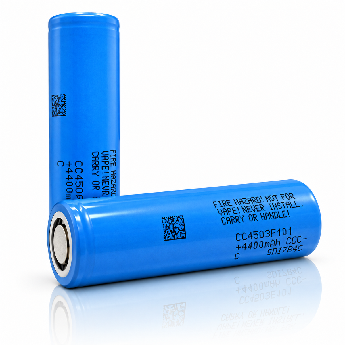
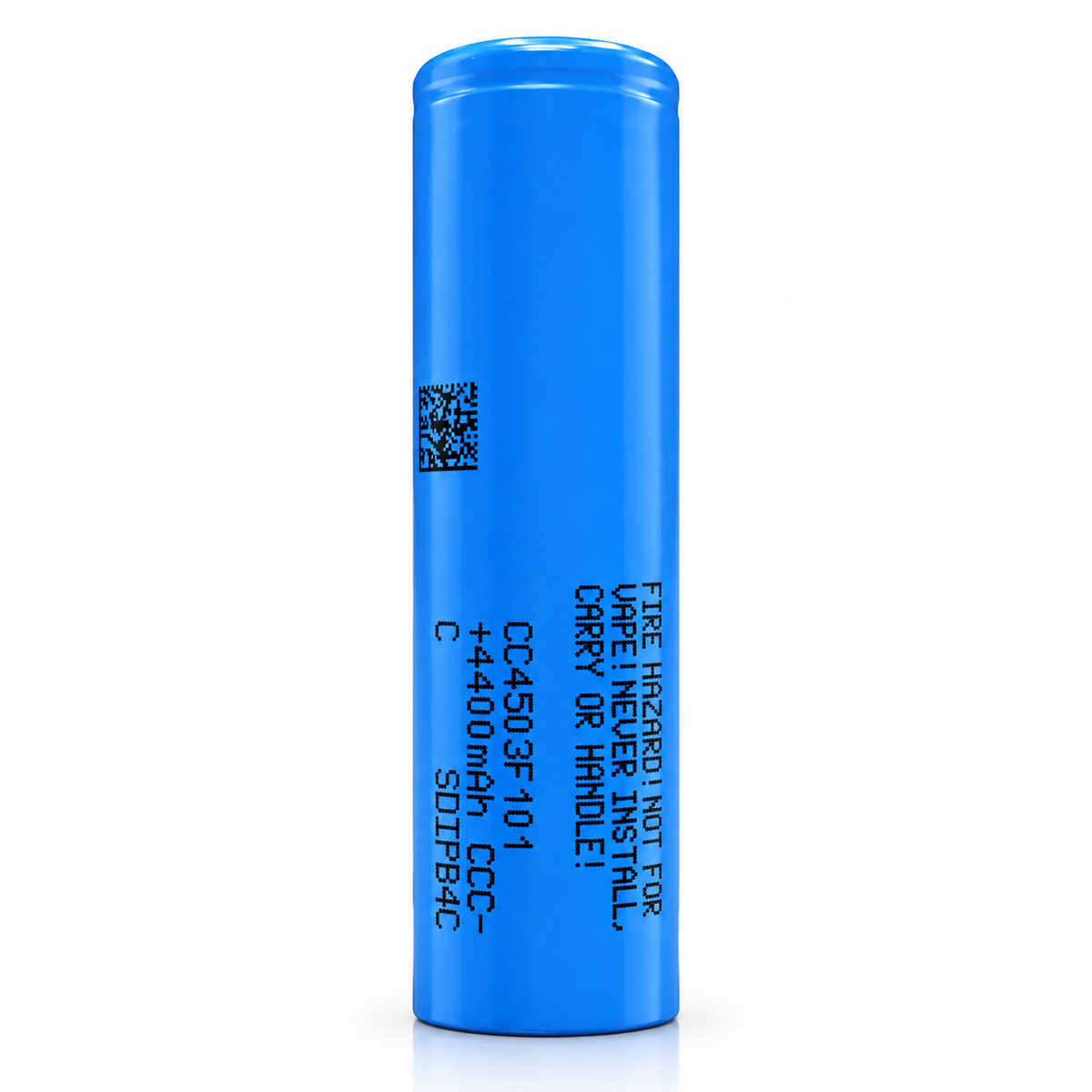


A 21700 lithium-ion cell: “Typ. 4,500mAh” and “Min. 4,400mAh” at 0.2C, a rated minimum of 4,300 mAh at 10 A, and two continuous maximums, “35A(Without temperature cut)” and “50A(With 80℃ temperature cut)” [1]. Samsung SDI’s documents identify the cell as model CC4503F101; the name 45T, which we list it under, is printed in none of the three we hold: the specification [1], the safety data sheet (SDS) [2] and the UN38.3 transport test report [3]. Samsung SDI marks the specification confidential and it is a draft, so we quote it here but don’t link it (section 11 below). Below: every rating with its condition, the figures Samsung SDI prints in its tables and reports, and what we calculated from them, so you can check each number.
The SDS is linked. The specification and the UN38.3 report are on file but not linked (section 11 below). The library holds data sheets where the manufacturer publishes one.
A bare cell: a component for protected packs and devices built for it. Not for vaping. Charge on a lithium-ion (Li-ion) charger that stops at 4.2 V.
01SPEC PLATE
Every rating, with its condition.
Samsung SDI’s data sheet for this cell is titled Specification of Product [1]; this page calls it the specification. The only version we hold is V0.1, dated 2024-02-01. It is marked “Draft”, and its footer says the official version “will be valid only with separate written confirmation by Samsung SDI Co. Ltd.” Its ratings come first, copied as printed, with the energy figure from Samsung SDI’s UN38.3 report [3]. Then the capacity figures its tables print, our arithmetic, and facts from the safety data sheet (SDS) [2] and the UN38.3 report. Each row names its source or shows its formula.
| SPECIFICATION | VALUE | CONDITION · SOURCE |
|---|---|---|
| RATED · MANUFACTURER copied from specification [1]; the energy row from Samsung SDI’s UN38.3 report [3] | ||
| MODEL | CC4503F101 | SDI Model, Spec. No. and §2.2 model name, as printed [1]; the SDS [2] and the UN38.3 report [3] print the same code; no document prints the name 45T |
| CAPACITY, TYPICAL | 4,500 mAh | “Typ. 4,500mAh”; charge “0.5C(2.25A), 4.20V, 0.05C(225mA) cut-off @ RT”; discharge “0.2C(0.9A), 2.5V cut-off @ RT” [1] §3.1; RT is “23± 3℃(@RT)” [1] §6.1 |
| CAPACITY, MINIMUM | 4,400 mAh | “Min. 4,400mAh”, printed beside it, same condition [1] §3.1 |
| CAPACITY, RATED | 4,300 mAh | “Min. 4,300mAh”, “Rated discharge capacity”; charge “6A, 4.20V, 100mA cut-off @RT”; discharge “10A, 2.5V cut-off @ RT” [1] §3.2 |
| ENERGY | 16.2 Wh | printed “3.6 V 4500 mAh 16.2Wh (min 4400 mAh, 15.84Wh)” under “Ratings” on the cover of Samsung SDI’s UN38.3 report [3]; [1] prints no Wh for the cell; the SDS’s 15.5 Wh, on its 4.3 Ah basis, is in the second plate’s SDS and UN38.3 group |
| 1C | 4,500 mA | “*1C=4,500mA”: the basis of every 45T C-rate on this page [1] §3.1 |
| NOMINAL VOLTAGE | 3.6 V | “3.6V” [1] §3.3 |
| CHARGE VOLTAGE | 4.20 V | CC-CV, constant current then constant voltage; “4.20 V” in §3.4 and §3.5, “4.2V” in §7.1; no tolerance printed [1] |
| DISCHARGE CUT-OFF | 2.5 V | “2.5V (End of discharge)” [1] §3.9 |
| STANDARD CHARGE | 2.25 A | “CCCV, 2.25A, 4.20 V, 225mA cut-off”; “Standard charge : 150min / 225mA cut-off(@ RT)” [1] §3.4, §3.6 |
| RATED CHARGE | 6 A | “CCCV, 6A, 4.20 V, 100mA cut-off”; “Rated charge: 75min / 100mA cut-off(@ RT)” [1] §3.5, §3.6 |
| MAX. CHARGE, CONTINUOUS | 6 A | “6A (continuous charge)”, under “3.8 Max. charge current” [1] §3.8 |
| MAX. CHARGE, STEP CHARGE | 9 A | “9A (for step charge)”; [1] prints no step-charge profile (steps, voltages, durations) and no charging time at 9 A [1] §3.8 |
| MAX. CONTINUOUS DISCHARGE, NO CUT | 35 A | “35A(Without temperature cut)”, under “3.7 Max. continuous discharge (Surface temperature)” [1] §3.7 |
| MAX. CONTINUOUS DISCHARGE, 80 °C CUT | 50 A | “50A(With 80℃ temperature cut)” [1] §3.7; Note (*²): discharge over-temperature protection “should not be over 80℃ of Cell surface temperature”; §3.15 adds “(must re-discharge release < 60℃)” [1] |
| PULSE DISCHARGE | Not stated | Not stated by manufacturer: no pulse, peak or other non-continuous discharge figure in [1], [2] or [3] |
| CHARGE TEMPERATURE, AMBIENT | −10 to 60 °C | “Charge : -10 to 60℃(-10 to 0 : Safety performance only)”, “(Ambient)” [1] §3.14 |
| CHARGE TEMPERATURE, PACK DESIGN GUIDELINE | 0 to 60 °C | “Charge temperature ranges : 0℃ ~ 60℃” [1] pack design guideline 1.1.2; this page says not to charge below 0 °C |
| DISCHARGE TEMPERATURE, AMBIENT | −20 to 60 °C | “Discharge: -20 to 60℃”, “(Ambient)” [1] §3.14 |
| CHARGE TEMPERATURE, SURFACE | −10 to 60 °C | the same line, with “(-10 to 0 : Safety performance only)”; “(recommended recharge release < 45℃)”; “(Surface)” [1] §3.15 |
| DISCHARGE TEMPERATURE, SURFACE | −20 to 80 °C | “Discharge: -20 to 80℃”; “(must re-discharge release < 60℃)”; “(Surface)”; Note (*²) [1] §3.15 |
| AC IMPEDANCE | ≤ 10 mΩ | “Initial internal impedance ≤ 10mΩ”, at AC 1 kHz after Rated charge [1] §7.5 |
| CYCLE LIFE AT 35 A | ≥ 2,700 mAh | “① Capacity ≥ 2,700mAh @ after 250cycles”; 6 A CC-CV charge to 4.20 V, 100 mA cut-off; 35 A discharge to 2.5 V; @ RT; “(60% of the standard capacity @ RT)” [1] §3.10 |
| CYCLE LIFE AT 50 A | ≥ 2,700 mAh | “② Capacity ≥ 2,700mAh @ after 100cycles”; the same charge; 50 A discharge to 2.5 V “(80℃ cut-off, re-discharge release < 50℃)” @ RT; “(60% of the standard capacity @ RT)” [1] §3.10 |
| AFTER STORAGE AT 60 °C | ≥ 3,870 mAh | “Capacity recovery(after the storage) ≥ 3,870 mAh”; rated charge, “30 days (@ 60℃)”, then 10 A to 2.5 V @ RT; “(90% of the rated capacity @ RT)” [1] §3.11 |
| RECOVERY 90 % AFTER STORAGE | −20 to 23 °C | for 1 year; −20 to 45 °C for 3 months; −20 to 60 °C for 1 month; Note (*³): kept “as ex-factory status (30% of charge)” [1] §3.16 |
| STORAGE | 0 to 23 °C | “0 ~ 23℃, low humidity (below 65%)” [1] proper use 3.1.1; pack design guideline 1.3: “below 60℃, 20℃ is recommended” [1] |
| AS SHIPPED | 3.532–3.572 V | “The cell should be shipped in 3.532V to 3.572V charging voltage range.” [1] §7.11; ex-factory status “(30% of charge)”, Note (*³) |
| DIAMETER | 21.35 mm | “Diameter : Max 21.35mm” [1] §3.13; Fig. 1 “With tube” |
| HEIGHT | 70.62 mm | “Height : Max 70.62mm” [1] §3.13; Fig. 1 “With tube” |
| MASS | 72.0 g | “72.0g max” [1] §3.12 |
| TERMINAL | Not stated | Not stated by manufacturer: Fig. 1 is an outline labeled only with its maximum dimensions, “Unit : mm” and “With tube” [1] |
| PROTECTION | Not stated | Not stated by manufacturer: no document describes a protection circuit on the cell; Note (*¹) puts protection in the battery pack [1] |
| + Source: [1] Samsung SDI, “Specification of Product”, “Draft”, Spec. No. CC4503F101, Version No. V0.1, Date of Application 24/02/01 (as printed, YY/MM/DD), 23 pages; “3.SDI Model : CC4503F101”; every page headed “SAMSUNG SDI Confidential Proprietary” and watermarked with the name of the company it was issued to; its footer says the document “is a draft and is provided for information only”; the only version on file; not linked from this page, because Samsung SDI marks it confidential and it is a draft. Call or text with questions about it + Source: [3] Samsung SDI, “UN TEST REPORT”, “Test Summary”, Report Number SDI-UN-231031-01, Ver.00, Date of issue 2023.10.31, Test period 2021.09.30 ~ 2021.10.17 (as printed), 10 pages; Model Name CC4503F101; test standard “Recommendations on the Transport of Dangerous Goods: Manual of Tests and Criteria, section 38.3 Seventh revised edition”; Samsung SDI Co., Ltd is named as both the testing laboratory and the manufacturer, Cheonan, Korea: the maker’s own laboratory; on file, and quoted here but not linked, because its cover prints a person’s contact details. Call or text to ask about it | ||
| SPECIFICATION | VALUE | CONDITION · SOURCE |
|---|---|---|
| PRINTED IN THE SPECIFICATION’S TABLES percent of the 4,300 mAh index “(=4,300mAh)”, the 10 A discharge at 23 °C, as printed; mAh calculated [1] | ||
| CAPACITY AT 20 A | 95 % | ≈ 4,085 mAh; 20 A to 2.5 V after the rated charge [1] §7.8 |
| CAPACITY AT 30 A | 93 % | ≈ 3,999 mAh; the same condition [1] §7.8 |
| CAPACITY AT 40 A, A TEST CURRENT | 90 % | ≈ 3,870 mAh; above “35A(Without temperature cut)”; no temperature cut printed for the run [1] §7.8 |
| DISCHARGE AT −20 °C, 10 A | 60 % | ≈ 2,580 mAh; after the rated charge [1] §7.6 |
| DISCHARGE AT 60 °C, 10 A | 95 % | ≈ 4,085 mAh; after the rated charge [1] §7.6 |
| CHARGED AT 0 °C | 80 % | ≈ 3,440 mAh; discharged at 23 °C, 10 A [1] §7.7 |
| CALCULATED arithmetic on [1], [2] and [3], shown so you can check it | ||
| CONTINUOUS DISCHARGE AS C-RATE | 7.78C · 11.11C | 35 A “(Without temperature cut)” and 50 A “(With 80℃ temperature cut)” ÷ 4.5 A, the printed “*1C=4,500mA” [1] §3.7 |
| MAX. CHARGE AS C-RATE | 1.33C · 2.00C | “6A (continuous charge)” and “9A (for step charge)” ÷ 4.5 A [1] §3.8 |
| RUNTIME AT 30 A | 8.0 min | 3,999 mAh ÷ 30 A, from [1] §7.8; 5.8 min at the 40 A test current |
| ENERGY CHECK | 16.20 · 15.84 Wh | 3.6 V × 4,500 mAh and 3.6 V × 4,400 mAh: the two figures [3] prints; 3.6 V × 4.3 Ah = 15.48 Wh, which rounds to the SDS’s 15.5 Wh [2] |
| PRE-CHARGE CURRENT | 450–2,250 mA | 0.1–0.5 × 4,500 mA: “with a charging current of 0.1 ~ 0.5C”, pack design guideline 1.1.8 [1] |
| VOLUME | 25.3 cm³ | π × (21.35 mm ÷ 2)² × 70.62 mm ≈ 25,282 mm³, from the maximum size [1]; an upper bound |
| FROM THE SAFETY DATA SHEET (SDS) AND UN38.3 TRANSPORT TEST REPORT copied as printed from [2] and [3] | ||
| CHEMISTRY | Li-ion | [1] prints “Lithium-ion Battery” and no cathode chemistry; the SDS prints “Cathode (positive electrode): based on lithiated metal oxide (Cobalt, Nickel, Aluminium)” [2] 1.5 |
| ENERGY, SDS | 15.5 Wh | “Wh rating: 15.5 Wh”, with “Rated Capacity: 4.3 Ah”, no condition printed [2] 1.5 |
| RATED CAPACITY, SDS | 4.3 Ah | “Rated Capacity: 4.3 Ah”, no condition printed [2]; the same figure as the 4,300 mAh rated minimum at 10 A [1]; [3] prints “4500 mAh” with no label |
| TRANSPORT | UN3480 · Class 9 | “14.1 UN Number : 3480”; “14.3 Transport Hazard class : 9 (applicable for air transport)”; “14.6 Packing instructions : P903”; “14.10 IATA Transport : PI 965-Section IB”; UN3481 when packed with or contained in equipment [2] |
| UN38.3 | SDI-UN-231031-01 | Ver.00, Date of issue 2023.10.31, Test period 2021.09.30 ~ 2021.10.17; T-1 to T-6 and T-8 “PASS”, T-7 “N/A”, remark “Battery only”; Samsung SDI’s own laboratory; cited, not linked [3] |
| SAFETY DATA SHEET | Rev. 00 | “Revision no.: 00”, “Date: 28 May 2024”; “MODEL CC4503F101”; linked [2] |
| STORAGE · SDS | ≈ 20 °C | “Storage at room temperature (approx. 20℃) at approx. 40% of the nominal capacity” [2] 7.2; [1]’s own storage clauses are in the first plate |
| + Source: [1] Samsung SDI, “Specification of Product”, “Draft”, Spec. No. CC4503F101, Version No. V0.1, Date of Application 24/02/01 (as printed, YY/MM/DD), 23 pages; “3.SDI Model : CC4503F101”; every page headed “SAMSUNG SDI Confidential Proprietary” and watermarked with the name of the company it was issued to; its footer says the document “is a draft and is provided for information only”; the only version on file; not linked from this page, because Samsung SDI marks it confidential and it is a draft. Call or text with questions about it + Source: [2] Samsung SDI, “Safety Data Sheet”, “MODEL CC4503F101”, “Revision no.: 00”, “Date: 28 May 2024”, 25 pages; prepared “In accordance with Regulation (EU) 2020/878 (REACH), Annex II, and OSHA 29 CFR 1910.1200”; no validity period printed; its closing section XVI begins “Product safety data sheet for INR21700-50U”, as printed, while its page headers and section 1.1 name the CC4503F101 · SDS PDF + Source: [3] Samsung SDI, “UN TEST REPORT”, “Test Summary”, Report Number SDI-UN-231031-01, Ver.00, Date of issue 2023.10.31, Test period 2021.09.30 ~ 2021.10.17 (as printed), 10 pages; Model Name CC4503F101; test standard “Recommendations on the Transport of Dangerous Goods: Manual of Tests and Criteria, section 38.3 Seventh revised edition”; Samsung SDI Co., Ltd is named as both the testing laboratory and the manufacturer, Cheonan, Korea: the maker’s own laboratory; on file, and quoted here but not linked, because its cover prints a person’s contact details. Call or text to ask about it | ||
Voltage window
Black marks: the voltages [1] prints in §3.3, §3.4 and §3.9. Orange band: the shipping voltage, 3.532–3.572 V [1] §7.11; ex-factory status is “(30% of charge)”, Note (*³). The band sits just below the 3.6 V nominal voltage.
Current limits
Currents as [1] prints them, in A, each with its condition. C-rates labeled calculated are our arithmetic, current ÷ the printed “*1C=4,500mA”; the standard charge’s 0.5C is printed in [1] §3.1 and §7.1. Gray: 9 A, printed only “for step charge”, with no step-charge profile. 50 A holds only “(With 80℃ temperature cut)” [1] §3.7; Note (*²) sets that cut at no more than 80 °C on the hottest cell surface. [1] prints no pulse or other non-continuous discharge figure.
Temperature envelope
Operating ranges from [1] §3.14 “(Ambient)” and §3.15 “(Surface)”. Orange: charge, 0 to 60 °C, where this page says to charge. Gray: −10 to 0 °C, which both charge rows mark “(-10 to 0 : Safety performance only)” and where this page says not to charge; the pack design guideline prints “Charge temperature ranges : 0℃ ~ 60℃” (fig 5.3). The marks at 60 and 45 °C are §3.15’s release temperatures: discharge may resume only below 60 °C, and recharging is recommended to resume below 45 °C. 80 °C: Note (*²)’s ceiling for discharge over-temperature protection, set at the hottest cell. Last row: the §7.6 and §7.7 test temperatures (section 04 below).
Recovery 90 % after storage, by duration
Storage time and temperature, as [1] §3.16 prints them under “3.16 Recovery 90% after storage(*³)”. Note (*³): “If Cell is kept as ex-factory status (30% of charge), the capacity recovery rate shall be more than 90%.” [1] prints other storage statements, each in its own words (fig 6.2).
Capacity, as each document prints it
Each document’s capacity figure, as printed, on a 4,200–4,600 mAh scale; the axis doesn’t start at zero. “Rated” means the same figure in two documents: [1]’s rated discharge capacity is the 4,300 mAh minimum at 10 A, and the SDS prints “Rated Capacity: 4.3 Ah” with no condition. Only [1] calls 4,500 mAh typical; [3] prints it with no label. None of the three documents prints a higher capacity.
Energy, by document
Wh as printed in [3] and [2], beside our arithmetic; [1] prints no Wh for the cell. Each printed figure matches 3.6 V × the capacity printed with it: 4,500 mAh (16.2 Wh) and 4,400 mAh (15.84 Wh) in [3], 4.3 Ah in [2] (15.48 Wh, printed 15.5). Scale 15.0–16.5 Wh; the axis doesn’t start at zero.
93 % of 4,300 mAh at 30 A.
In [1] §7.8, Samsung SDI prints the capacity at 10, 20, 30 and 40 A as a percent of 4,300 mAh: its 10 A discharge at 23 °C, the same figure as its rated minimum (§3.2). At 30 A, the highest of the four below the 35 A continuous maximum “(Without temperature cut)”, it prints 93 %: about 3,999 mAh, or about 8.0 min at 30 A by our arithmetic. Its 40 A point, 90 %, is a test current above that maximum and below the 50 A one “(With 80℃ temperature cut)”, with no temperature cut printed for the run.
Data: [1] §7.8, Discharge rate capabilities · after the rated charge, to 2.5 V · 23 °C for the 10 A index; [1] prints no temperature for the 20–40 A runs, and §6.1 sets “23± 3℃” unless otherwise specified · percent of the 4,300 mAh index, mAh calculated · the line joins the four printed points; Samsung SDI prints no curve between them · 40 A is a test current above “35A(Without temperature cut)” · axis starts at 3,750 mAh · data table under fig 3.1
03BY CURRENT
Capacity and runtime, by current.
[1] §7.8 prints the capacity at 10, 20, 30 and 40 A, to 2.5 V after the rated charge, as a percent of the 4,300 mAh index. The mAh, the C-rates and the runtimes are arithmetic on those figures, with the formula under each. It prints no point at 35 A, the continuous maximum without a temperature cut, or at 50 A, the one with the 80 °C cut.
Capacity delivered, by current
Capacity to 2.5 V at each current, after the rated charge, printed in [1] §7.8 as a percent of the 4,300 mAh index “(=4,300mAh)”, the 10 A discharge at 23 °C; mAh = percent × 4,300, rounded half up; C-rate = current ÷ the printed 4.5 A 1C. Orange: 40 A, a test current above the 35 A continuous maximum “(Without temperature cut)”; [1] prints no temperature cut for these runs. The table prints no point at the two continuous maximums, 35 A without a temperature cut and 50 A with the 80 °C cut.
DATA TABLE · FIG 3.1
| CURRENT | C-RATE | PRINTED % | mAh | RUNTIME |
|---|---|---|---|---|
| 10 A | 2.22C | 100 | 4,300 | 25.8 min |
| 20 A | 4.44C | 95 | 4,085 | 12.3 min |
| 30 A | 6.67C | 93 | 3,999 | 8.0 min |
| 40 A | 8.89C | 90 | 3,870 | 5.8 min |
Runtime at a constant current
Runtime = capacity ÷ current, from the mAh in fig 3.1: one full rated charge, constant current to 2.5 V. A device whose average draw is below its peak current runs longer than the figure at that peak.
35 A or 50 A?
- 35 A is the continuous maximum “35A(Without temperature cut)” [1] §3.7.
- 50 A is the continuous maximum “50A(With 80℃ temperature cut)” [1] §3.7. Something has to stop the discharge before the surface of the hottest cell passes 80 °C (Note (*²)) and let it resume only once that surface is below 60 °C, “(must re-discharge release < 60℃)” §3.15. In a pack, that is a temperature sensor on the hottest cell, read by the battery management system (BMS); in a device, its own cell-temperature cut-off.
- At 50 A the cut-off can stop the discharge before the cell is empty: [1] prints no capacity at 50 A; its rate table stops at 40 A.
- The cycle-life figures follow the same split: at least 2,700 mAh after 250 cycles at 35 A, and after 100 cycles at 50 A with “(80℃ cut-off, re-discharge release < 50℃)” [1] §3.10, a cooler release than the 60 °C limit in §3.15.
- [1] §7.8 runs a 40 A test, above the 35 A continuous maximum without a temperature cut, with no temperature cut printed for the run: 90 % of 4,300 mAh. A test current, not a rating.
- [1] prints no pulse, peak or other non-continuous discharge figure, so none is left out here.
- Its proper-use section says the cell “shall be discharged continuously at less than maximum discharge current specified in the product specification” [1] 2.1.
- If you don’t know whether your device stops the discharge before the cell surface passes 80 °C, plan for 35 A.
04TEMPERATURE
Capacity in the cold and the heat.
Two tables in [1]: §7.6, capacity when a 10 A discharge runs at −20, −10, 0, 23 and 60 °C after the rated charge; and §7.7, capacity after a rated charge at 0, 5, 23, 45 and 60 °C, discharged at 23 °C. Both print a percent of 4,300 mAh. At −20 °C, the bottom of the discharge range in [1], it prints 60 %.
Capacity, by discharge temperature
Capacity when the 10 A discharge runs at each temperature, to 2.5 V, after the rated charge, which [1] §7.2 sets at 23 °C; where the charge and discharge temperatures differ, [1] sets a 3-hour interval for the temperature change. Printed in [1] §7.6 as a percent of the 4,300 mAh index; mAh calculated. Orange: below 0 °C. −20 °C is the bottom of the discharge range in [1] §3.14 and §3.15.
DATA TABLE · FIG 4.1
| DISCHARGE °C | PRINTED % | mAh | RUNTIME AT 10 A |
|---|---|---|---|
| −20 °C | 60 | 2,580 | 15.5 min |
| −10 °C | 75 | 3,225 | 19.4 min |
| 0 °C | 80 | 3,440 | 20.6 min |
| 23 °C | 100 | 4,300 | 25.8 min |
| 60 °C | 95 | 4,085 | 24.5 min |
Capacity, by charge temperature
Capacity of a 10 A discharge to 2.5 V at 23 °C, after a rated charge at each temperature, printed in [1] §7.7 as a percent of the 4,300 mAh index; mAh calculated. Orange: 0 °C, the lowest charge temperature in the table and in the pack design guideline’s “0℃ ~ 60℃”. [1] prints no figure for a charge below 0 °C; §3.14 marks −10 to 0 °C “(-10 to 0 : Safety performance only)”.
DATA TABLE · FIG 4.2
| CHARGE °C | DISCHARGE °C | PRINTED % | mAh |
|---|---|---|---|
| 0 °C | 23 °C | 80 | 3,440 |
| 5 °C | 23 °C | 90 | 3,870 |
| 23 °C | 23 °C | 100 | 4,300 |
| 45 °C | 23 °C | 95 | 4,085 |
| 60 °C | 23 °C | 95 | 4,085 |
Reading the two tables
- §7.6 runs the discharge at each temperature after a rated charge at 23 °C; §7.7 charges at each temperature and discharges at 23 °C. Both use 10 A to 2.5 V and print a percent of the 4,300 mAh index [1].
- At −20 °C, [1] prints 60 %: about 2,580 mAh, or about 15.5 min at 10 A by our arithmetic, against 25.8 min at 23 °C.
- Charged at 0 °C, 80 %; at 5 °C, 90 % [1] §7.7. [1] prints no capacity after a charge below 0 °C.
- The discharge range is −20 to 60 °C ambient and −20 to 80 °C at the cell surface [1] §3.14, §3.15; the tables stop at 60 °C.
- Neither table runs at a continuous maximum, 35 A without a temperature cut or 50 A with the 80 °C cut: both use 10 A.
05CHARGING
Charging: 2.25 A standard, 6 A rated.
The specification prints a 2.25 A standard charge, CC-CV to 4.20 V with a 225 mA cut-off in 150 min, and a 6 A rated charge with a 100 mA cut-off in 75 min [1] §3.4–§3.6. Its max. charge current is “6A (continuous charge)”, with “9A (for step charge)” beside it and no step-charge profile. Its cycle-life figures charge at 6 A. Charge between 0 and 60 °C, the range of its pack design guideline [1].
Charge time, as printed
Charging time as [1] §3.6 prints it: “Standard charge : 150min / 225mA cut-off(@ RT)” and “Rated charge: 75min / 100mA cut-off(@ RT)”. [1] prints no charging time and no step-charge profile (steps, voltages, durations) for “9A (for step charge)”, so that row has no bar. Bars start at zero.
Voltage thresholds for a pack
Voltage thresholds for a pack’s battery management system (BMS): the cell ratings in [1], and the pre-charge, re-charge and do-not-charge levels from the pack design guideline printed in [1]. Orange: the working range. The re-charge mark sits at 4.1 V, our arithmetic (4.20 V − 0.1 V), the highest the guideline allows. Below 1.0 V, the guideline says not to charge the cell at all.
Charge temperature
Where [1] allows charging. §3.14 (ambient) and §3.15 (cell surface) print −10 to 60 °C and mark −10 to 0 °C “Safety performance only” (gray); the pack design guideline prints 0 to 60 °C. Orange: 0 to 60 °C, where this page says to charge. The mark at 45 °C is §3.15’s “(recommended recharge release < 45℃)”. Last row: the §7.7 charge temperatures (fig 4.2).
Before you charge
- Use a lithium-ion charger with a CC-CV profile that stops at 4.2 V; [1]’s pack design guideline prints “Cut-off Voltage of charging must be 4.2V.”
- 2.25 A (0.5C) is the standard charge, 150 min to the 225 mA cut-off; 6 A is the rated charge, 75 min to 100 mA [1] §3.4–§3.6. The most [1] allows continuously is “6A (continuous charge)”; “9A (for step charge)” comes with no step-charge profile, so we give none. Its proper-use section says charging current “should be less than maximum charge current specified in the product specification” [1] 1.1.
- Charge between 0 and 60 °C. [1] §3.14 prints −10 to 60 °C but marks −10 to 0 °C “(-10 to 0 : Safety performance only)”, and its pack design guideline prints “Charge temperature ranges : 0℃ ~ 60℃”. Below 0 °C, don’t charge.
- Don’t charge a cell that has fallen below 1.0 V; the pack design guideline in [1] says not to. Between 1.0 and 3.0 V it calls for a pre-charge at 0.1–0.5C (450–2,250 mA by our arithmetic).
- In a pack, a BMS (battery management system) should end charge at 4.2 V per cell and stop a charge on charging time or current; §3.15 prints “(recommended recharge release < 45℃)” for the cell surface [1].
Fig 5.2 plots values that the pack design guideline in [1] prints as text; Samsung SDI draws no chart of them. The guideline matches the cell ratings: charge cut-off “must be 4.2V”, discharge cut-off “must be over 2.5V” [1]. [1] prints no capacity-by-charge-current table; fig 4.2 shows capacity by charge temperature.
06CYCLE LIFE AND STORAGE
What it keeps after use and storage.
[1] specifies at least 2,700 mAh after 250 cycles at 35 A, and after 100 cycles at 50 A with an 80 °C cut-off, and at least 3,870 mAh after 30 days at 60 °C. It prints no cycle-life curve, so the page shows only these points. It also prints several storage statements, each worded differently, and the SDS adds its own (figs 6.2 and 6.3).
Capacity after storage and cycling
Capacities as [1] prints them: typical and minimum when new, minimums after storage and cycling. New: [1] §3.1 and §3.2. After storage: 30 days at 60 °C from the rated charge, then 10 A to 2.5 V, “(90% of the rated capacity @ RT)” [1] §3.11. After cycling: 6 A CC-CV charge to 4.20 V with a 100 mA cut-off, and discharge to 2.5 V at room temperature, at 35 A for 250 cycles or at 50 A with “(80℃ cut-off, re-discharge release < 50℃)” for 100 cycles; both “(60% of the standard capacity @ RT)” [1] §3.10. 2,700 mAh is 60 % of the 4,500 mAh typical (our check). Orange: the cycle-life floors. Figures, not a warranty, and not a curve: [1] prints no capacity between the first cycle and the last.
Storage temperature, by statement
The storage statements in [1], each in its own words, and the SDS’s, cited separately; [1] doesn’t reconcile its own. Orange: [1]’s proper-use range, 0 to 23 °C, which this page follows. Marks: 20 and 60 °C on the pack design guideline row, 20 °C on the SDS row. For 3 months or more, [1] §11.1 says “It is strongly recommended that Cell is preserved at dry and low-temperature.”
Storage charge, by document
State of charge for storage, as each document prints it, on different bases. [1] gives the ex-factory status as “(30% of charge)” and says that for long-term storage a cell shall be “stored at shipping voltage” (proper use 3.2.2); the SDS gives “approx. 40% of the nominal capacity”. The two differ; this page follows [1].
07TRANSPORT TESTS
What Samsung SDI’s UN38.3 report records.
Samsung SDI’s UN38.3 report [3] records “PASS” for T-1 to T-6 and T-8 on model CC4503F101; T-7, overcharge, is printed “N/A” with the remark “Battery only”. Samsung SDI Co., Ltd is named as both the testing laboratory and the manufacturer: the maker’s own laboratory, not an independent one. The tests ran from 2021-09-30 to 2021-10-17, and the report was issued 2023-10-31, so it describes a manufacturer sample, not our lot. Its tables print what each cell did. It also records P1, a package drop test: a “1.2m drop test” of a box of 130 cells, “Without release of contents”. We quote the report but don’t link it, because its cover prints a person’s contact details.
Highest temperature, by abuse test
Highest external temperature of each cell, as printed in [3]: one tick per cell; the bar spans the lowest to the highest. T5 external short circuit: 10 fully charged cells, 5 at first cycle and 5 after 25 cycles (sample conditions A and B). T6 impact (the report ticks impact, not crush): 10 cells at 50 % charge, 5 at first cycle and 5 at the 25th. [3] prints no short-circuit resistance, impact mass or drop height. T8 forced discharge: 20 fully discharged cells, 10 at first cycle and 10 after 25 cycles, “Initial test current : 35A, Test duration : 8min”: a test condition, not a rating. [3] prints no T8 temperatures, so T8 has no row. Pass criteria, condensed: T5 and T6, not over 170 °C, with no disassembly or fire (T5: or rupture) within 6 h; T8, no disassembly or fire within 7 days. [3] marks all 40 samples “O”: no disassembly and no fire, and in T5 no rupture.
DATA TABLE · FIG 7.1
| TEST | SAMPLE CONDITION, AS PRINTED | CELLS | MAX °C, EACH CELL | RANGE |
|---|---|---|---|---|
| T5 external short, first cycle | A: at first cycle, in fully charged states(5 pcs) | 5 | 84.2, 72.4, 81.3, 80.4, 85.6 | 72.4–85.6 °C |
| T5 external short, after 25 cycles | B: after 25th cycles ending in fully charged states(5 pcs) | 5 | 81.8, 94.6, 87.6, 78.2, 82.9 | 78.2–94.6 °C |
| T6 impact, first cycle | C: at first cycle, in 50% charged states(5 pcs) | 5 | 26.8, 25.3, 25.9, 26.2, 24.9 | 24.9–26.8 °C |
| T6 impact, 25th cycle | D: at 25th cycle, in 50% charged states(5 pcs) | 5 | 25.5, 26.7, 25.8, 25.1, 25.1 | 25.1–26.7 °C |
Voltage kept through T1–T4
Open-circuit voltage after each test, as a percent of the voltage before it, as printed in [3]; one mark per printed value. The same 10 cells ran T1 to T4: each test’s before-values repeat the previous test’s after-values. [3] prints 4.164–4.169 V before T1 and 4.085–4.093 V after T4, and no test parameters for T1 to T4. The scale starts at 85 %.
Mass of the cells in the report
Mass of the 10 cells Samsung SDI’s laboratory weighed before T1, as printed in [3]: 69.632–70.102 g (mean 69.805 g, our arithmetic), against the 72.0 g maximum in [1] §3.12 and on the cover of [3]. Across T1 to T4 the printed weights run 69.627–70.165 g. After T2 all ten weighed 0.059–0.068 g more than before it, while [3] prints “Percent of Weight Loss(%)” as 0.00 for each; after T3 it prints 0.09–0.10 %. P1 lists a “Cell weight (kg)” of 0.07016. The axis starts at 69.4 g. A 2021 manufacturer sample, not our lot.
DATA TABLE · FIG 7.3
| CELL | CONDITION | BEFORE T1 g | AFTER T1 | AFTER T2 | AFTER T3 | AFTER T4 |
|---|---|---|---|---|---|---|
| 1 | A | 69.713 | 69.713 | 69.777 | 69.712 | 69.711 |
| 2 | A | 69.764 | 69.761 | 69.825 | 69.760 | 69.759 |
| 3 | A | 69.758 | 69.760 | 69.819 | 69.757 | 69.756 |
| 4 | A | 69.680 | 69.678 | 69.745 | 69.676 | 69.676 |
| 5 | A | 69.632 | 69.629 | 69.694 | 69.628 | 69.627 |
| 6 | B | 69.839 | 69.835 | 69.902 | 69.833 | 69.833 |
| 7 | B | 70.102 | 70.097 | 70.165 | 70.095 | 70.095 |
| 8 | B | 70.091 | 70.088 | 70.155 | 70.085 | 70.085 |
| 9 | B | 69.748 | 69.745 | 69.812 | 69.742 | 69.742 |
| 10 | B | 69.722 | 69.722 | 69.787 | 69.718 | 69.718 |
Safety tests the specification lists
| TEST | THE MAKER’S TEST METHOD, CONDENSED FROM [1] | PASS CRITERION, AS PRINTED | SECTION |
|---|---|---|---|
| Drop | Fully standard-charged cells dropped onto a concrete floor from 1.0 m, 3 times, in random orientations; at least 1 h of rest, then a visual inspection | “No fire, no explosion.” | [1] §8.1 |
| Vibration | Per UN38.3, for each axis (X and Y for cylindrical cells): 7 Hz → 200 Hz → 7 Hz in 15 min, repeated 12 times, 3 h in total; 1 g from 7 to 18 Hz, and 8 g (amplitude 1.6 mm) to 200 Hz | “No leakage, with less than 10% of OCV drop” | [1] §8.2 |
| Overcharge | Cell discharged at 1.0 A to 2.5 V, then charged at 4.6 V and 27 A for 7 h | “No fire, and no explosion.” | [1] §9.1 |
| External short-circuit | Fully rated-charged cell shorted through an 80 ± 20 mΩ load until fire or explosion, or until it is below 0.2 V and its case is back within ± 10 °C of ambient; run at 20 ± 5 °C and at 55 ± 5 °C | “No fire, and no explosion” | [1] §9.2 |
| Forced discharge | Discharged cell reverse-charged at 1.0C (4.5 A) for 90 min | “No fire, and no explosion.” | [1] §9.3 |
| Heating | The “rate charged” cell (as printed) heated at 5 °C per minute to 130 °C, then held 30 min in an oven | “No fire, and no explosion.” | [1] §9.4 |
The maker’s test methods, condensed in our words from [1] §8 and §9, and its pass criteria as printed. [1] prints no results for these tests. Their voltages and currents, such as 4.6 V and 27 A in the overcharge test, are test conditions, not ratings. [1] also names a test standard for each method; apart from the UN38.3 report [3], we hold no certificate or report for them, so they are not listed. The UN38.3 results above are a different set of tests, from [3].
08COMPARE
Where the 45T sits.
Fifteen other 21700 cells, each from its own data sheet. Three print a higher discharge figure than the 45T’s 50 A “(With 80℃ temperature cut)”: the Molicel P50B, 60 A with an 80 °C cut-off, and the Tenpower 60XG, 60 A with a 75 °C cut-off, both with a higher minimum capacity too; and the EVE 40PL, whose 70 A is printed as a maximum with a temperature cut-off, not as continuous. Nine print a higher minimum capacity than the 45T’s 4,400 mAh at 0.2C. Without a temperature cut, the 45T’s continuous maximum is 35 A [1]. On that basis, the Tenpower 60XG prints 40 A without its cut-off, the Samsung 40T the same 35 A and the Samsung 50S 25 A; the Molicel P45B and P42A print 45 A with no condition at all. The conditions behind each figure differ, so the table quotes each sheet’s wording.
Minimum capacity and discharge, side by side
- EVE 40PL INR21700/40PL4,000 mAh minimum · no typical printed70 A maximum, not called continuous · with temperature cut-off, TMax 80 °C
- Tenpower 60XG INR21700-60XG5,900 mAh minimum · 6,000 nominal60 A continuous · 75 °C cut-off; 40 A without
- Molicel P50B INR-21700-P50B4,850 mAh minimum · 5,000 typical60 A continuous · 80 °C cut-off
- Samsung 45T CC4503F1014,400 mAh minimum at 0.2C · 4,500 typical50 A continuous · 80 °C temp. cut; 35 A without
- Samsung 50S INR21700-50S4,800 mAh rated minimum at 10 A · 5,000 typical45 A continuous · 80 °C temp. cut; 25 A without
- Molicel P45B INR-21700-P45B4,350 mAh minimum · 4,500 typical45 A max. continuous · no condition printed
- Samsung 40T INR21700-40T4,000 mAh minimum · no typical printed45 A continuous · 80 °C temp. cut; 35 A without
- Molicel P42A INR-21700-P42A4,000 mAh minimum · 4,200 typical45 A continuous · no condition printed
- Sony/Murata VTC6A US21700VTC6A4,000 mAh minimum · 4,160 nominal40 A continuous max. · 80 °C temp. cut
- Molicel M65A 21700-M65A6,400 mAh minimum · 6,500 ± 70 at 0.2C; no typical label25.6 A rating type not printed · 90 °C cut-off; preliminary
- EVE 50E INR21700/50E4,900 mAh minimum · 5,000 nominal15 A max. continuous · no condition printed
- Molicel M50A INR-21700-M50A4,800 mAh minimum · 5,000 typical15 A continuous · no condition printed
- Samsung 50G INR21700-50G (Ver. B)4,900 mAh minimum · no typical printed14.7 A continuous · −20 to 30 °C; 9.8 A at 31 to 60 °C
- LG M50LT INR21700M50LTMinimum not stated by manufacturer · no mAh capacity printed14.4 A max. · 10 to 25 °C; 7.2 A at 25 to 55 °C, 2.4 A at −20 to 10 °C
- Samsung 58E CC5493F101 (Ver. A)5,330 mAh minimum · no typical mAh printed10.66 A 2C for continuous discharge · 10.66 A = 2 × 5,330 mA, our arithmetic
- Samsung 50E INR21700-50E4,900 mAh minimum · no typical printed9.8 A for continuous discharge · no condition printed
Each cell’s figures copied from its own data sheet [1][4]. Bars start at zero: minimum capacity on a 0–7,000 mAh scale, discharge on 0–70 A. The condition sits beside each current; where a sheet prints two continuous figures, the bar shows the higher and the condition names the other. The EVE 40PL’s 70 A is printed as a maximum, not as continuous. The 58E’s 10.66 A is our arithmetic, 2 × 5,330 mA. The 50S’s 4,800 mAh is its rated minimum at 10 A; the 45T’s 4,400 mAh is at 0.2C, and its rated minimum at 10 A is 4,300 mAh [1]. The M65A sheet is preliminary R&D data. Pulse and other non-continuous figures are left out.
| CELL | TYPICAL OR NOMINAL mAh | MINIMUM mAh | DISCHARGE AS PRINTED | CHARGE AS PRINTED | MASS g |
|---|---|---|---|---|---|
|
EVE 40PL INR21700/40PL |
not printed | 4,000 | Maximum Discharge: “70A(17.5C), 2.50V”, “With Temperature Cut-off”, “TRecommended: 75℃”, “TMax: 80℃” (a maximum; the word continuous is not printed) | Maximum Charge: “8.0A(2.0C), 4.20±0.05V, CCCV 0.1A cut-off” | 67.0 max |
|
Tenpower 60XG INR21700-60XG |
6,000 nominal | 5,900 | Max. continuous discharge current: “40A (without temperature cut off)” and “60A(with 75℃ temperature cut-off)” | Max. charging current: “16A” (no condition printed) | 76.0 max |
|
Molicel P50B INR-21700-P50B |
5,000 typical | 4,850 | Discharge Current, Continuous: “60 A (80°C cut-off)” | Charge Current, Maximum: “25 A (70°C cut-off)” | 71 max |
| Samsung 45T CC4503F101 |
4,500 typical | 4,400 minimum at 0.2C | Max. continuous discharge (Surface temperature): “35A(Without temperature cut)” and “50A(With 80℃ temperature cut)” | Max. charge current: “6A (continuous charge)” and “9A (for step charge)” (no step-charge profile printed) | 72.0 max |
|
Samsung 50S INR21700-50S |
5,000 typical | 4,800 rated minimum at 10 A | Max. continuous discharge (Surface temperature): “25A(Without temperature cut)” and “45A(With 80℃ temperature cut)” | Max. charge current: “6A (continuous charge)” | 72.0 max |
|
Molicel P45B INR-21700-P45B |
4,500 typical | 4,350 | Maximum continuous discharging current: “45A” (no condition printed; remark: “Cycle life is reduced at high rates.”) | Maximum continuous charging current: “9A” (remark: “High rate charge cycle will decay fast.”) | 70 max |
|
Samsung 40T INR21700-40T |
not printed | 4,000 | Max. continuous discharge (Surface temperature): “35A(Without temperature cut)” and “45A(With 80℃ temperature cut)” | Rated charge: “CCCV, 6A, 4.20 V, 100mA cut-off” (this spec prints no separate max. charge current item) | 70 max |
|
Molicel P42A INR-21700-P42A |
4,200 typical | 4,000 | Discharge Current, Continuous: “45 A” (no condition printed) | not on the Version 1.7 data sheet (Charge Current, Standard: 4.2 A); Doc # INR21700P42A-01 Rev. 0.2: Maximum charging current: “8.4A, See Section 4.14” | 70 max |
| Sony/Murata VTC6A US21700VTC6A |
4,160 nominal | 4,000 | Continuous Maximum Discharging Current: “40A (With 80deg.C temperature cut)” | Maximum Charging Current: “6A (Continuous)” | not printed placeholder “xx ±1.5g” |
| Molicel M65A 21700-M65A |
6,500 “Capacity (0.2C): 6500 mAh ± 70 mAh”; no typical or nominal label printed | 6,400 | Discharge current: “25.6A (90℃cut-off)” (the word continuous is not printed; preliminary R&D data) | Charge current: “6.5A (Standard)” and “6.5A (Max)” | 72.5 ± 1.5, as printed |
|
EVE 50E INR21700/50E |
5,000 nominal | 4,900 | Max Continuous Discharge current: “15000” mA (no condition printed) | Max. Continuous Charge current: “2500” mA (§5.9); Operating Temperature Range, Charging Temp.: “15~50” °C, “≤5000mA” (§5.12); 12.2.1 b: “Charge rates greater than 5000mA are not recommended.” | 69.0 ± 2.0, as printed; no maximum printed |
| Molicel M50A INR-21700-M50A |
5,000 typical | 4,800 | Discharge Current, Continuous: “15 A” (no condition printed) | not on the V3 data sheet (Charge Current, Standard: 2.5 A); Doc # INR21700M50A-01 Rev. 0.1: Maximum charging current: “5.0A” | 70 max |
| Samsung 50G INR21700-50G (Ver. B) |
not printed | 4,900 | Max. Discharge Current (*²): “3C (14,700mA, for continuous discharge @ -20℃~30℃)” and “2C (9,800mA, for continuous discharge @ 31℃~60℃)” | Max. Charge Current: “4,900mA (not for cycle life)” | 71 max |
| LG M50LT INR21700M50LT |
not printed no mAh capacity printed; energy 18.2 Wh nominal, 17.6 Wh minimum | Not stated by manufacturer | Max. Discharge Current (complete full charge)²⁾: “-20 ~ 10℃ 0.5C (2,400mA)”, “10 ~ 25℃ 3.0C(14,400mA)”, “25 ~ 55℃ 1.5C(7,200mA)” (its note 2) calls these the maximum continuous currents) | Max. Charge Current (complete full charge)²⁾: “0 ~ 25℃ 0.3C (1,440mA)” and “25 ~ 45℃ 0.7C (3,360mA)” | 68.2 ± 1.0, with tube and washer |
|
Samsung 58E CC5493F101 (Ver. A) |
not printed “(Typ. 20.0 Wh)” only | 5,330 | Max. Discharge Current (*²): “2C (for continuous discharge)”; “*1C=5,330 mA” (the non-continuous figure is not shown; 10.66 A = 2 × 5,330 mA is our arithmetic) | Max. Charge Current: “1C (not for cycle life)”; “*1C=5,330 mA” | 74 max |
|
Samsung 50E INR21700-50E |
not printed | 4,900 | Max. Discharge Current: “9,800mA (for continuous discharge)” (the non-continuous figure is not shown) | Max. Charge Current: “4,900mA (not for cycle life)” | 69.5 max |
Labels as printed; text in quotation marks is copied exactly from each manufacturer data sheet [1][4], newest version in our files, checked by a second reading; notes in parentheses are ours. Several of these sheets are marked draft, tentative or preliminary; Sources gives each version as printed. Links go to the bare-cell listing in our store; cells without a link aren’t listed there.
09PACK MATH
From one cell to a pack.
How the single-cell ratings scale in series (S) and parallel (P). Illustrative arithmetic, not a pack rating.
charge voltage, 4.20 V [1]
nominal voltage, 3.6 V [1]
Ah, minimum at 0.2C; 4.3 × P at 10 A [1]
A without a temperature cut; 50 × P only with the 80 °C cut [1] §3.7*
| CONFIG | CELLS | V MAX | V NOMINAL | Ah MINIMUM | Wh AT MINIMUM Ah | A, NO TEMPERATURE CUT* | A, WITH 80 °C CUT* | CELL MASS g, MAX |
|---|---|---|---|---|---|---|---|---|
| 1S1P | 1 | 4.2 | 3.6 | 4.4 | 15.84 | 35 | 50 | 72.0 |
| 2S1P | 2 | 8.4 | 7.2 | 4.4 | 31.68 | 35 | 50 | 144.0 |
| 3S1P | 3 | 12.6 | 10.8 | 4.4 | 47.52 | 35 | 50 | 216.0 |
| 4S1P | 4 | 16.8 | 14.4 | 4.4 | 63.36 | 35 | 50 | 288.0 |
| 2S2P | 4 | 8.4 | 7.2 | 8.8 | 63.36 | 70 | 100 | 288.0 |
| 3S2P | 6 | 12.6 | 10.8 | 8.8 | 95.04 | 70 | 100 | 432.0 |
| 4S2P | 8 | 16.8 | 14.4 | 8.8 | 126.72 | 70 | 100 | 576.0 |
| 7S3P | 21 | 29.4 | 25.2 | 13.2 | 332.64 | 105 | 150 | 1,512.0 |
| 10S3P | 30 | 42.0 | 36.0 | 13.2 | 475.20 | 105 | 150 | 2,160.0 |
| 10S4P | 40 | 42.0 | 36.0 | 17.6 | 633.60 | 140 | 200 | 2,880.0 |
| 13S4P | 52 | 54.6 | 46.8 | 17.6 | 823.68 | 140 | 200 | 3,744.0 |
| 14S5P | 70 | 58.8 | 50.4 | 22.0 | 1,108.80 | 175 | 250 | 5,040.0 |
Continuous current ceiling, by parallel count
The single-cell continuous maximums [1] §3.7 times the parallel count: 35 A “(Without temperature cut)” and 50 A “(With 80℃ temperature cut)”; our arithmetic. Ceilings before derating, not pack ratings.
* Multiplies a single-cell maximum by the number of cells in parallel: 35 A “(Without temperature cut)”, or 50 A “(With 80℃ temperature cut)”, which needs a pack that stops discharge before the hottest cell surface passes 80 °C (Note (*²)) and resumes only below 60 °C, “(must re-discharge release < 60℃)” [1] §3.15. [1]’s proper-use section asks for continuous discharge at less than the maximum, so treat each figure as a ceiling, not a working current. Cells in a pack run hotter than one cell on a bench and reach the 80 °C cut-off sooner: derate, and size the BMS, fusing and interconnects for the derated current. Wh = 3.6 V × 4.4 Ah × S × P, the 15.84 Wh minimum that [3] prints, times the cell count. Samsung SDI’s pack design guideline in [1] also asks for second protective devices, “such as PTC & PCM at the same time”, so one still protects the cell if the other fails (a PTC is a resettable positive-temperature-coefficient fuse; a PCM, a protection circuit module), more than 1 mm between cells, a pack current “under 10uA after shut down”, monitoring of each cell block’s voltage, and, for every application category in its mechanical-design table, partitions between the BMS and the cells and a “non-flammable (VO level) case”. Mass counts cells only. The UN38.3 report [3] covers the bare cell, not your pack; a pack you build needs its own UN38.3 testing before it ships as UN3480.
10SIZE AND FIT
Ø21.35 × 70.62 mm, maximum.
Drawn at its printed maximum, with tube, beside nominal 18650 and 21700 outlines. [1] prints maximum dimensions only, with no nominal size or tolerance. Check tight holders against the Ø21.35 mm and 70.62 mm maximums.
Drawn to scale
All outlines drawn to the same scale. The 45T at its maximum with tube [1] §3.13, Fig. 1; the other outlines are nominal format sizes, for scale only.
| DIMENSION | VALUE | CONDITION |
|---|---|---|
| Diameter | 21.35 mm | “Diameter : Max 21.35mm” [1] §3.13; Fig. 1 “With tube” |
| Height | 70.62 mm | “Height : Max 70.62mm” [1] §3.13; Fig. 1 “With tube” |
| Mass | 72.0 g | “72.0g max” [1] §3.12 |
| Terminal | Not stated | Not stated by manufacturer: Fig. 1 labels no top style [1] |
| Volume | 25.3 cm³ | π × (21.35 mm ÷ 2)² × 70.62 mm ≈ 25,282 mm³, from the maximum size [1]; an upper bound |
Check that your holder or device takes a cell 70.62 mm long and 21.35 mm across, the maximums in [1]. [1] doesn’t state the top style. Spot-weld nickel strip for packs; don’t solder to the cell.
11USE IT RIGHT
Keep it inside its ratings.
What this cell is, and how to use it within its ratings.
- This is a bare cell: a component for protected packs and devices built for it. It is not a standalone consumer battery and not for vaping.
- No document we hold describes a protection circuit on the cell; Samsung SDI describes its cells as designed to be built into a battery management unit [1] (handling precaution 3.6.2). [1] doesn’t state the top style: check that your device takes a cell 70.62 mm long and 21.35 mm across, the maximums in [1].
- Charge on a lithium-ion (Li-ion) charger that stops at 4.2 V, between 0 and 60 °C, never below 0 °C. Stop discharging at 2.5 V [1].
- Stay inside the ratings [1]: discharge at no more than 35 A continuous “(Without temperature cut)”, or 50 A only “(With 80℃ temperature cut)”, between −20 and 60 °C ambient; charge at the 2.25 A standard or 6 A rated charge, “6A (continuous charge)” at most.
- Don’t leave, charge or use cells where it may get hotter than 60 °C, such as a closed car; don’t heat a cell above 100 °C, take it apart or burn it [1].
- Keep cells away from children [1]. Don’t use a cell with a torn wrap, a dented can or an electrolyte smell: [1] says a cell “should not be used if sleeve-damage, can-distortion and/or electrolyte-smell is detected” (proper use 5.1.2). Carry cells in a case, never loose.
- For packs: matched cells of one model and lot, a BMS, second protective devices “such as PTC & PCM at the same time” (pack design guideline 1.5), more than 1 mm between cells, and a place away from heat sources [1]; add fusing sized for the pack.
Questions? Call 1-800-547-3050 or text 1-833-419-2192 to ask a person.
Documents
The SDS [2], Rev. 00 dated 2024-05-28, is linked, unaltered, as posted on our store. The specification [1] and the UN38.3 report [3] are on file but not linked; this page quotes and cites both. [1] is not linked because it is V0.1, a draft dated 2024-02-01, with every page headed “SAMSUNG SDI Confidential Proprietary” and watermarked with the name of the company it was issued to. [3] is not linked because its cover prints a person’s contact details; it comes from Samsung SDI’s own laboratory, which ran its tests from 2021-09-30 to 2021-10-17 and issued it 2023-10-31. None of the three cites another by number or version; they share the model code CC4503F101. We hold no released (non-draft) specification, no transport test from an independent laboratory, no certificate or report, apart from [3], for the safety tests [1] lists, and no results from our own lot. Call or text to ask about any of them. The data-sheet library lists sheets where the manufacturer publishes one; [1] is not in it.
Ships from Stockbridge, GA. Most in-stock orders ship within 1 business day.
12QUESTIONS
Questions, answered.
Short answers. Where an answer comes from a document, it carries its source; the rest is standard handling practice. Anything else: call 1-800-547-3050 or text 1-833-419-2192.
Is the 45T a protected cell?
It is sold as a bare cell: a component for packs and devices that provide their own protection. No document we hold describes a protection circuit on the cell. [1] puts protection in the pack: Note (*¹) says “Protection function of the battery pack should be set within the specified charge, discharge and temperature range in Cell Specification.” Its handling precautions describe Samsung SDI’s cells as designed to be built into a battery management unit (3.6.2). Use it only in packs with a battery management system (BMS) or in devices built for bare cells. [1] doesn’t state the top style.
Does the specification say 45T?
No. None of the three Samsung SDI documents we hold prints 45T or INR21700-45T. All three identify the cell as model CC4503F101: the specification [1], the SDS [2] and the UN38.3 report [3], whose sample photo shows the same code on the cell. 45T is the name we list it under. Every 45T rating on this page comes from those documents; results from our own lot are not shown (section 13 below).
Is it a 4,500 mAh cell?
Typically. [1] prints “Typ. 4,500mAh” with “Min. 4,400mAh” beside it, both at 0.2C (0.9 A) to 2.5 V after a 0.5C standard charge at room temperature, and a rated minimum, “Min. 4,300mAh”, at 10 A after the 6 A rated charge [1] §3.1, §3.2. Plan on 4,400 mAh at low current and 4,300 mAh at 10 A. The SDS prints “Rated Capacity: 4.3 Ah” [2]; the UN38.3 report prints “4500 mAh” with no label [3]. The tables in [1] §7.6–§7.8 use 4,300 mAh as 100 %.
35 A or 50 A: which is its continuous current?
Both, each with its condition [1] §3.7. Without a temperature cut-off it is “35A(Without temperature cut)”. With one it is “50A(With 80℃ temperature cut)”: the device or pack must stop the discharge before the surface of the hottest cell passes 80 °C (Note (*²)) and let it resume only below 60 °C, “(must re-discharge release < 60℃)” §3.15. At 50 A that cut-off can stop the discharge before the cell is empty; [1] prints no capacity above 40 A. If you don’t know whether your device has that cut-off, plan for 35 A, and plan each cell in a pack for less: [1] says the cell “shall be discharged continuously at less than maximum discharge current specified in the product specification” (proper use 2.1). [1] prints no pulse or other non-continuous discharge figure; the cycle-life figures for each current are in section 06 above.
Is it a 50 A cell?
Only with a temperature cut-off. [1] prints 50 A only with an 80 °C cut: as the rating “50A(With 80℃ temperature cut)” (§3.7), and in its 100-cycle test with “(80℃ cut-off, re-discharge release < 50℃)” (§3.10). The discharge has to stop before the cell surface passes 80 °C. Without that cut-off, [1] prints “35A(Without temperature cut)”. A 50 A figure shown on its own drops the condition [1] attaches to it. [1] prints no pulse or other non-continuous discharge figure, so a figure above 50 A does not come from this specification. We publish both, each with its condition.
How fast can I charge it?
At most 6 A continuous: [1]’s max. charge current is “6A (continuous charge)” (§3.8), the same 6 A as its rated charge, CC-CV to 4.20 V with a 100 mA cut-off, in 75 min; the standard charge is 2.25 A (0.5C) with a 225 mA cut-off, in 150 min [1] §3.4–§3.6. [1] also prints “9A (for step charge)”, but no step-charge profile and no charging time at 9 A, so we give none. Its proper-use section says charging current “should be less than maximum charge current specified in the product specification” [1] 1.1. Charge between 0 and 60 °C: [1] §3.14 marks −10 to 0 °C “(-10 to 0 : Safety performance only)”, and its pack design guideline prints “Charge temperature ranges : 0℃ ~ 60℃”.
What charger should I use?
A lithium-ion charger with a CC-CV profile (constant current, then constant voltage) that stops at 4.2 V. [1]’s pack design guideline prints “Cut-off Voltage of charging must be 4.2V.” and asks the charger to stop on charging time or current. Not a NiMH, LiFePO4 or lead-acid charger.
How long will it run at my current?
Runtime ≈ capacity ÷ current. Calculated from [1] §7.8, after a full rated charge: about 25.8 min at 10 A, 12.3 min at 20 A, 8.0 min at 30 A, and 5.8 min at the 40 A test current (fig 3.2); the mAh are the printed percent × 4,300 mAh. For your own draw, divide 4,300 mAh by your current in mA to get hours, then take the share [1] prints nearest your current: 95 % at 20 A, 93 % at 30 A, 90 % at the 40 A test current (fig 3.1); at −20 °C, 60 % at 10 A (fig 4.1). [1] prints no capacity above 40 A.
How does cold affect it?
At −20 °C, the bottom of its discharge range, [1] §7.6 prints 60 % of the 4,300 mAh index at 10 A, about 2,580 mAh; it prints 75 % at −10 °C and 80 % at 0 °C, against 100 % at 23 °C. Charged at 0 °C, a 10 A discharge at 23 °C gives 80 % [1] §7.7. [1] prints no capacity after a charge below 0 °C; don’t charge below 0 °C.
How many cycles will it last?
[1] gives no lifetime cycle count. It prints two minimums, both at room temperature and both “(60% of the standard capacity @ RT)”: at least 2,700 mAh after 250 cycles of 6 A charge (CC-CV to 4.20 V, 100 mA cut-off) and 35 A discharge to 2.5 V, and after 100 cycles with a 50 A discharge and “(80℃ cut-off, re-discharge release < 50℃)” [1] §3.10. Both use full charges and high-current discharges; [1] prints nothing for lighter use or other temperatures, and no curve. Heat, current, depth of discharge and storage all change the result.
Is there an SDS or a UN38.3 test report?
Both are on file. The SDS [2], “Revision no.: 00”, “Date: 28 May 2024”, names “MODEL CC4503F101” and is linked on this page. The UN38.3 report [3], SDI-UN-231031-01 Ver.00, issued 2023-10-31 by Samsung SDI’s own laboratory, records “PASS” for T-1 to T-6 and T-8 (section 07 above). We quote it but don’t link it, because its cover prints a person’s contact details. If you need it to ship cells or packs, call or text before you order.
How does it ship?
The SDS gives “14.1 UN Number : 3480”, “14.2 UN Proper shipping name : LITHIUM ION BATTERIES”, “14.3 Transport Hazard class : 9 (applicable for air transport)”, “14.6 Packing instructions : P903” and “14.10 IATA Transport : PI 965-Section IB” [2], and UN3481 when the cells are packed with or contained in equipment. Samsung SDI’s UN38.3 report [3] covers the CC4503F101 cell; the tests ran from 2021-09-30 to 2021-10-17. A pack built from these cells needs its own UN38.3 testing.
What chemistry is it?
Lithium-ion. [1] prints “Lithium-ion Battery” and “Cell (lithium-ion rechargeable cell)”, and no cathode chemistry. The SDS prints “Cathode (positive electrode): based on lithiated metal oxide (Cobalt, Nickel, Aluminium)” [2] 1.5.
Can I use it in a vape or e-cigarette?
No. It is a bare cell: a component for protected packs and devices built for it, not for vaping. Samsung SDI’s specification says “Samsung SDI’s cells are not designed or manufactured for use in any vape or e-cigarette devices.” [1] (handling precaution 3.6.1).
Can I solder to it?
Don’t solder directly to the cell: Samsung SDI’s handling precautions say “Don't solder on the battery directly.” [1] 2.3.9, and its pack design guideline asks for leads welded to the cell’s terminals rather than soldering cells to each other [1] 2.1.1. Spot-weld nickel strip, or use a holder.
Can I mix 45T cells with other cells?
No, not in the same pack. [1] says “Do not mix use Cells from different batches/ranks even they are the same Cell types from the same manufacturer.” (proper use 6.5.2) and “Don't use or assemble old and new batteries together.” (handling precaution 2.3.13). Use cells of one model and lot, at the same state of charge. In series, the weakest cell reaches 2.5 V first and limits the whole pack, and mismatched cells drift further apart with each cycle.
How should I store spare cells?
At 0 to 23 °C and below 65 % humidity, at shipping voltage (3.532–3.572 V), in a case away from metal objects. [1] prints several storage statements, each worded differently: its proper-use section says “0 ~ 23℃, low humidity (below 65%)”; its pack design guideline says “below 60℃, 20℃ is recommended”; its recovery table gives more than 90 % recovery after 1 year at −20 to 23 °C, for a cell kept at the ex-factory 30 % charge (fig 1.4); and for long-term storage it says a cell “shall be stored at shipping voltage” (proper use 3.2.2). Storage at 0 to 23 °C, below 65 % humidity, sits inside all three temperature statements (our reading). The SDS adds “Storage at room temperature (approx. 20℃) at approx. 40% of the nominal capacity” [2]; this page follows [1]. Check the voltage every few months.
13SOURCES
Sources and method.
Where every number on this page comes from.
- + Source: [1] Samsung SDI, “Specification of Product”, “Draft”, Spec. No. CC4503F101, Version No. V0.1, Date of Application 24/02/01 (as printed, YY/MM/DD), 23 pages; “3.SDI Model : CC4503F101”; every page headed “SAMSUNG SDI Confidential Proprietary” and watermarked with the name of the company it was issued to; its footer says the document “is a draft and is provided for information only”; the only version on file; not linked from this page, because Samsung SDI marks it confidential and it is a draft. Call or text with questions about it
- + Source: [2] Samsung SDI, “Safety Data Sheet”, “MODEL CC4503F101”, “Revision no.: 00”, “Date: 28 May 2024”, 25 pages; prepared “In accordance with Regulation (EU) 2020/878 (REACH), Annex II, and OSHA 29 CFR 1910.1200”; no validity period printed; its closing section XVI begins “Product safety data sheet for INR21700-50U”, as printed, while its page headers and section 1.1 name the CC4503F101 · SDS PDF
- + Source: [3] Samsung SDI, “UN TEST REPORT”, “Test Summary”, Report Number SDI-UN-231031-01, Ver.00, Date of issue 2023.10.31, Test period 2021.09.30 ~ 2021.10.17 (as printed), 10 pages; Model Name CC4503F101; test standard “Recommendations on the Transport of Dangerous Goods: Manual of Tests and Criteria, section 38.3 Seventh revised edition”; Samsung SDI Co., Ltd is named as both the testing laboratory and the manufacturer, Cheonan, Korea: the maker’s own laboratory; on file, and quoted here but not linked, because its cover prints a person’s contact details. Call or text to ask about it
- + Source: [4] Samsung 40T: INR21700-40T data sheet, Spec. No. INR21700-40T, Version No. 0.0, December, 2017 (headed “SAMSUNG SDI Confidential Proprietary”; every page watermarked “Tentative”; no version suffix); on file
- + Source: [4] Samsung 50E: INR21700-50E data sheet, Spec. No. INR21700-50E, Version No. V1.0 (General Version), 2018/07/11; on file
- + Source: [4] Samsung 50G: INR21700-50G (Ver. B) data sheet, Spec. No. INR21700-50G, Version No. Draft V0.2, Date of Application 2023/05/10; on file
- + Source: [4] Samsung 50S: INR21700-50S data sheet, Spec. No. INR21700-50S, Version No. V1.0, Date of Application 2021/04/19; on file
- + Source: [4] Samsung 58E: CC5493F101 (Ver. A) data sheet, Spec. No. CC5493F101, Version No. Draft V0.1, Date of Application 2023/12/04; on file
- + Source: [4] Molicel P42A: INR-21700-P42A data sheet, Product Data Sheet Version: 1.7; max charge from Doc # INR21700P42A-01, Rev. 0.2, 8/17/2018; on file
- + Source: [4] Molicel P45B: INR-21700-P45B data sheet, Doc # INR21700P45B-01, Rev. 0.2, 2022/01/06 (Approval Sheet (tentative)); on file
- + Source: [4] Molicel P50B: INR-21700-P50B data sheet, Product Data Sheet Version 1.1; on file
- + Source: [4] Molicel M50A: INR-21700-M50A data sheet, Product Data Sheet, no version printed (file INR21700M50A-V3-80097, PDF dated 2020-04-01); max charge from Doc # INR21700M50A-01, Rev. 0.1, 6/4/2019; on file
- + Source: [4] Molicel M65A: 21700-M65A data sheet, R&D Update, M65A performance (preliminary); no version printed (file dated 2025.04.29); on file
- + Source: [4] LG M50LT: INR21700M50LT data sheet, Doc No. 2021-LSD-MBD-b00002, Rev 2, 2021-07-06 (marked “For (Promotion) only” and “This document is NOT final version”); on file
- + Source: [4] Sony/Murata VTC6A: US21700VTC6A data sheet, Tohoku Murata Spec. No. KU※※※※※, Ver. 0.1, 1st issue 2017.11.27 (Products Information, Tentative); on file
- + Source: [4] EVE 40PL: INR21700/40PL data sheet, Spec. No. PBRI-INR21700/40PL-D06-01, Version No. A, June, 2023; on file
- + Source: [4] EVE 50E: INR21700/50E data sheet, Document No. RD-EVE INR21700/50E-S76-LF, Edition A (initial release), Effective Date 2022.5.23; on file
- + Source: [4] Tenpower 60XG: INR21700-60XG data sheet, Spec. No. INR21700-60XG, Version No. V0.1 draft, Effective Date 2025/12/09 (draft; every page marked TENPOWER confidential proprietary); on file
- + Method: none of the documents we hold has a performance chart for this cell; [1] prints three relative-capacity tables (§7.6–§7.8) and its rating clauses. Every chart on this page plots a figure printed in [1], [2], [3] or [4], or arithmetic on those figures with the formula under it; where a line joins printed points, nothing between them is printed. The C-rates we calculate use the printed “*1C=4,500mA” [1] §3.1. mAh from a printed percent = percent × the 4,300 mAh index of [1] §7.6–§7.8, rounded half up. Each figure was copied from the document and checked against it by a second reading.
- + Not shown from [1]: its warranty clause (§10), written to Samsung SDI’s direct customer, with its resale and use terms; the rest of its vape and e-cigarette warning (handling precautions 3.6.3–3.6.5), which addresses handling by individual consumers (3.6.3), third parties selling its cells to individual consumers for vape devices (3.6.4), and online e-commerce and consumer sales (3.6.5); its packaging drawings and parts list (Figs. 2-1 to 2-5, stamped “CONFIDENTIAL”); its emergency contact page; and the test standards it names for its own safety tests (section 07 above).
- + Not shown from [2]: its hazard statements, classifications, toxicology and composition table. This page quotes only its identification lines (model, revision, date, regulation and the section XVI line), its transport identity, its cathode wording, its Wh rating with the “Rated Capacity: 4.3 Ah” it is printed with, and its storage line.
- + Not shown: results from our own lot. We will add them only once our incoming-inspection procedure is published, with sample size, instrument and date.