
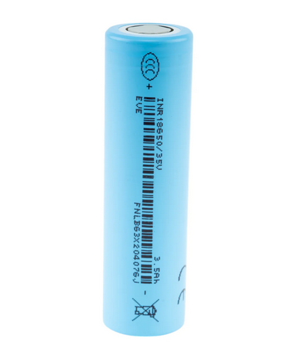
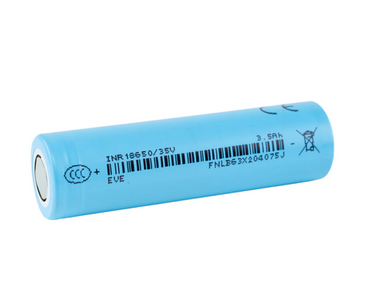
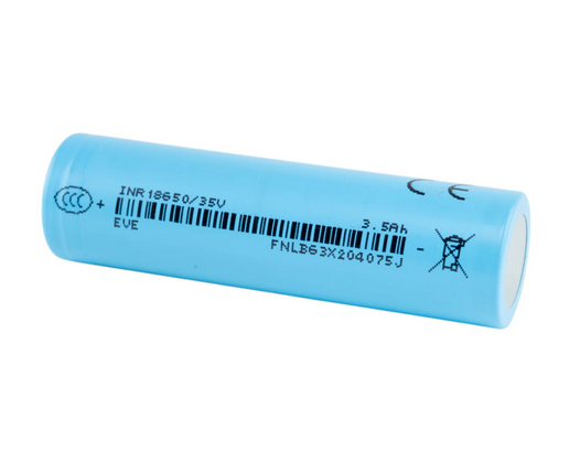


KEY SPECS · EVE ENERGY INR18650/35V
SOURCE [1]- SIZE
- Ø18.35 × 65.10 mm
- nominal ±0.10 / ±0.15 · with tube
- CAPACITY
- 3,500 mAh typ.
- 3,400 mAh min.
- 0.68 A to 2.50 V
- CURRENT
- Not stated by manufacturer
- continuous discharge
- TEMPERATURE
- −20 to 60 °C
- discharge · cell surface
- charge 0 to 50 °C · cell surface
An 18650 lithium-ion cell from EVE: 3,500 mAh typical and 3,400 mAh minimum, both from a 0.68 A discharge to 2.50 V [1] §3.1–§3.2, and a “Max. Discharge” of 10.2 A, “DC, 10.2A, 2.50V cut-off (Not for cycle life)” [1] §3.7. EVE calls no discharge current continuous; its cycle-life figure comes from a 1C discharge [1] §7.7, and [1]’s printed pairs “0.68A (0.2C)” and “10.2A(3C)” (§7.5) put 1C at 3.4 A (our arithmetic). Below: every printed figure with its condition, the percentages EVE’s tables print, the safety data sheet (SDS) and the UN38.3 report, and what we calculated from them, so you can check each number.
A bare cell: a component for protected packs and devices built for it. Not for vaping. Charge on a lithium-ion (Li-ion) charger, CCCV (constant current, then constant voltage), that stops at 4.20 V [1] §3.4. [1] is EVE’s specification, Spec. No. RD-EVE INR18650/35V-S161-LF, Version No. A, March, 2022. It is marked confidential, so we quote it and don’t link it.
01SPEC PLATE
Every figure, with its condition.
EVE’s document for the 35V is titled PRODUCT SPECIFICATION [1]; this page calls it the specification. Every page is marked “-EVE Energy CO., LTD Confidential and Proprietary-”, so we quote it and don’t link it. Its figures come first, copied as printed. Then the percentages its tables print, our arithmetic, and facts from the safety data sheet (SDS) [2] and the UN38.3 transport test report [3]. Each row names its source or shows its formula.
| ITEM | VALUE | CONDITION · SOURCE |
|---|---|---|
| AS PRINTED · MANUFACTURER copied from specification [1], Spec. No. RD-EVE INR18650/35V-S161-LF | ||
| MODEL | INR18650/35V | “Model” in the header of every page of [1]; model name “EVE-INR18650/35V” [1] §2.2 |
| CAPACITY, TYPICAL | 3,500 mAh | “3.1 Typical Discharge Capacity”; “Charge: 0.68A, 4.20V, CCCV 68mA cut-off”, “Discharge: 0.68A, 2.50V DC cut-off” [1] §3.1 |
| CAPACITY, MINIMUM | 3,400 mAh | “3.2 Min. Discharge Capacity”, the same charge and discharge [1] §3.2; “Discharge Capacity” “⩾ 3400mAh” with “discharge current of 0.68A (0.2C) with 2.50V cut-off at 25°C within 1 hour after the standard charge” [1] §7.3 |
| TYPICAL VOLTAGE | 3.65 V | “3.3 Typical Voltage”; no condition printed [1] §3.3 |
| CHARGE VOLTAGE | 4.20±0.05 V | “4.20±0.05V”, CCCV (constant current, then constant voltage), in “3.4 Standard Charge” and “3.5 Rapid Charge” [1] §3.4–§3.5 |
| DISCHARGE CUT-OFF | 2.50 V | “2.50V cut-off” in “3.6 Standard Discharge” and “3.7 Max. Discharge”; range “4.20~2.50V” [1] §3.6–§3.8 |
| STANDARD CHARGE | 0.68 A | “CCCV, 0.68A, 4.20±0.05V, 68mA cut-off” [1] §3.4; “charge current 0.68A (0.2C)”, “68mA cut-off in CV mode at 25°C” [1] §7.1 |
| RAPID CHARGE | 1.5 A | “CCCV, 1.5A, 4.20±0.05V, 68mA cut-off” [1] §3.5; “68mA cut-off in CV mode at 25°C” [1] §7.2; no C-rate or charge time printed |
| CHARGE, 0 TO 15 °C | ≤ 0.2C | “Charge: 0 to 15 °C”, “≤0.2C”, under “3.11 Operation Temperature (Surface Temperature)” [1] §3.11 |
| CHARGE, 15 TO 50 °C | ≤ 1.0C | “Charge: 15 to 50 °C”, “≤1.0C (Not for cycle life)”, cell surface [1] §3.11 |
| STANDARD DISCHARGE | 0.68 A | “DC, 0.68A, 2.50V cut-off” [1] §3.6 |
| MAX. DISCHARGE | 10.2 A | “DC, 10.2A, 2.50V cut-off (Not for cycle life)”, item “3.7 Max. Discharge” [1] §3.7; “10.2A(3C)” in the rate table [1] §7.5; no temperature or duration printed with it |
| DISCHARGE TEMPERATURE | −20 to 60 °C | “Discharge: -20 to 60°C(Pack cut-off temperature 70°C)”, cell surface [1] §3.11 |
| INTERNAL IMPEDANCE | ≤ 30 mΩ | “Initial Internal Impedance ≤ 30mΩ”, “at AC 1kHz at shipping SOC” [1] §7.4 |
| CYCLE LIFE | ≥ 70 % Ci | “Capacity ⩾ 70% Ci (the first cycle capacity at 25±2° C)” after 800 cycles of “Charge: CCCV, 0.5C to 4.2V, 170mA cut-off.” and “Discharge: DC, 1C to 3.0V cut-off.”, with “Rest time: 10min after charge and 30min after discharge.” [1] §7.7 |
| STORAGE, 1 YEAR AT SHIPPING SOC | 0 to 25 °C | “1 year” “0~25°C”; “3 months” “0~45°C”; “1 month” “0~60°C”; “3.12 Storage Temperature (At Shipping SOC)”; “The Recovery capacity is more than 90% of Min. capacity.” [1] §3.12 |
| STORAGE, 3 MONTHS OR MORE | 3.450–3.600 V | “3 months or more”: “one cycle”, then “from 3.450V to 3.600V”, “normally 0~25°C”, “dry and no corrosive gas” [1] §13.1 |
| SHIPPING VOLTAGE, AS SPECIFIED | 3.450–3.600 V | “The cell should be shipped in 3.450V to 3.600V charging voltage range (20~30% SOC).” [1] §7.9; what [1] requires, not a reading of our stock |
| DIAMETER | 18.35±0.10 mm | “Diameter: 18.35±0.10mm” [1] §3.10; “with tube” beside Fig. 1 [1] |
| HEIGHT | 65.10±0.15 mm | “Height: 65.10±0.15mm” [1] §3.10; “with tube” beside Fig. 1 [1] |
| WEIGHT, MAX | 50.0 g | “50.0g Max”, item “3.9 Cell Weight” [1] §3.9; no typical weight printed |
| TEST CONDITIONS | 25±2 °C | “Unless otherwise specified, all tests stated in this specification are conducted at temperature 25±2°C and humidity under 65% RH.” [1] §6.1 |
| + Source: [1] EVE Energy Co., Ltd., PRODUCT SPECIFICATION, Lithium-ion rechargeable cell, Model: EVE-INR18650/35V, Spec. No. RD-EVE INR18650/35V-S161-LF, Version No. A, March, 2022 (the cover date; as printed; the only version we hold; [1] prints no revision history); 15 scanned pages; quoted, not linked: every page is marked “-EVE Energy CO., LTD Confidential and Proprietary-”. Call or text to ask about it | ||
| ITEM | VALUE | CONDITION · SOURCE |
|---|---|---|
| PRINTED IN THE SPECIFICATION’S TABLES percent of each table’s own index, as printed: minimums, not readings [1] | ||
| CAPACITY AT 10.2 A | ≥ 90 % | “10.2A(3C)” “≥90%”, “2.50V cut-off after the standard charge”; “Relative capacity is divided by the discharge capacity of 0.68A.” [1] §7.5 |
| CAPACITY AT −20 °C | ≥ 70 % | “≥70%”, “after 3 hours storage at the test environment with discharge constant current 0.68A (0.2C) and 2.50V cut-off after the standard charge at 25°C”; “Relative capacity is divided by the 0.68A discharge capacity at 25°C.” [1] §7.6 |
| CAPACITY AT 55 °C | ≥ 90 % | “≥90%”, the same test at 55 °C [1] §7.6 |
| STORED 28 DAYS AT 25 °C | ≥ 85 % | retention “≥85%”, recovery “≥90%”, “25°C 28Days”, after a full standard charge; recovery is the standard discharge capacity over three cycles after the storage; both a percent of the “Initial Capacity: Standard discharge capacity.” [1] §7.8 |
| STORED 7 DAYS AT 60 °C | ≥ 85 % | retention “≥85%”, recovery “≥90%”, “60°C 7Days”; recovery over three cycles after the storage; the same basis [1] §7.8 |
| RECOVERY AFTER STORAGE AT SHIPPING SOC | > 90 % | “The Recovery capacity is more than 90% of Min. capacity.”, after the storage in “3.12 Storage Temperature (At Shipping SOC)” [1] §3.12 |
| CALCULATED arithmetic on [1], shown so you can check it | ||
| 1C | 3.4 A | 0.68 A ÷ 0.2 = 10.2 A ÷ 3 = 3.4 A, from “0.68A (0.2C)” §7.1 and “10.2A(3C)” §7.5; printed as “3.4A(1C)” in the §9.1 overcharge test, a test current [1]; [1] prints no 1C definition |
| CHARGE LIMIT, 15 TO 50 °C | ≤ 3.4 A | 1.0 × 3.4 A: “≤1.0C (Not for cycle life)”, cell surface [1] §3.11; not printed in amps |
| CHARGE LIMIT, 0 TO 15 °C | ≤ 0.68 A | 0.2 × 3.4 A: “≤0.2C”, cell surface [1] §3.11; not printed in amps |
| RAPID CHARGE AS C-RATE | 0.44C | 1.5 A ÷ 3.4 A = 0.441C [1] §3.5; [1] prints no C-rate for it |
| CYCLE-LIFE TEST CURRENTS | 1.7 · 3.4 A | “0.5C” charge = 0.5 × 3.4 A; “1C” discharge = 1 × 3.4 A [1] §7.7; not printed in amps |
| CHARGE CUT-OFFS AS C-RATE | 0.02C · 0.05C | “68mA cut-off” ÷ 3,400 mA [1] §3.4–§3.5; “170mA cut-off” ÷ 3,400 mA, the §7.7 cycle-life charge |
| ENERGY, CHECK | 12.775 Wh | 3.65 V “Typical Voltage” × 3.500 Ah typical capacity [1] §3.3, §3.1; equals the Wh printed in [2] and [3]; [1] prints no Wh |
| VOLUME | 17.2 cm³ | π × (18.35 ÷ 2)² × 65.10 mm³, the printed size with tube [1] §3.10; 16.99–17.44 cm³ at the tolerance limits |
| FROM THE SAFETY DATA SHEET (SDS) AND UN38.3 TRANSPORT TEST REPORT copied as printed from [2] and [3] | ||
| CHEMISTRY | Li-ion | [1] prints only “Lithium-ion rechargeable cell” (§2.1); the SDS composition lists “Cobalt lithium manganese nickel oxide”, 35.05 %, CAS 182442-95-1 [2] §3 |
| ENERGY | 12.775 Wh | “Ratings/额定参数” “3.65V, 3.5Ah, 12.775Wh” [2] §1; “Rating:” “3.65 Vdc, 3500 mAh, 12.775 Wh” [3] p.1; no condition printed with either; [1] prints no Wh |
| CAPACITY · SDS, UN38.3 | 3,500 mAh | “3.5Ah” [2] §1 and “3500 mAh” [3] p.1: the typical figure of [1], not its minimum |
| TRANSPORT | UN3480 or UN3481 | “UN number: UN3480 or UN3481;” air: “Class 9 (PI965 Section IB) or Not applicable (PI966〜967 Section II)”; sea: “not restricted according to IMO IMDG Code (inc. Amendment 42-24) Special Provision188” [2] §14 |
| UN38.3 REPORT · ISSUE DATE | 2022-02-17 | Report No. TW2112098-001, AnTek Certification Inc., “Date of Issued: Feb. 17, 2022”: “The sample has passed the test items of UN 38.3”; T1–T5, T6 “Impact” and T8 “Passed”; T6 “Crush” and T7 “N/A” [3] |
| SDS · ISSUE DATE | 2024-12-23 | Report No. HZYW20241128MSDS09, compiled by Guangzhou CPUP Certification Technology Service Co., Ltd.; Effective date 2025-01-01; no expiry printed; manufacturer printed as “EVE Innovation Energy Co.,Ltd.” [2] |
| STORAGE HUMIDITY · SDS | 60±25 % RH | “Long period storage: 25±5°C, 60±25%R.H” [2] §7; [1] prints no storage humidity. Its 25±5 °C runs to 30 °C, above [1]’s 1-year 0 to 25 °C; listed apart from [1]’s storage clauses, which lead |
| + Source: [1] EVE Energy Co., Ltd., PRODUCT SPECIFICATION, Lithium-ion rechargeable cell, Model: EVE-INR18650/35V, Spec. No. RD-EVE INR18650/35V-S161-LF, Version No. A, March, 2022 (the cover date; as printed; the only version we hold; [1] prints no revision history); 15 scanned pages; quoted, not linked: every page is marked “-EVE Energy CO., LTD Confidential and Proprietary-”. Call or text to ask about it + Source: [2] Guangzhou CPUP Certification Technology Service Co., Ltd., Material Safety Data Sheet (化学品安全技术说明书), Report No. HZYW20241128MSDS09, model INR18650/35V, Issue Date 2024-12-23, Effective date 2025-01-01 (as printed; no version or expiry printed) · SDS PDF + Source: [3] AnTek Certification Inc., Lithium Ion Battery Safety Testing Report (UN38.3), Report No. TW2112098-001, model INR18650/35V, Date of Issued: Feb. 17, 2022; tests performed Dec. 20, 2021 – Jan. 22, 2022, to the UN Manual of Tests and Criteria ST/SG/AC.10/11/Rev.6/Amend.1 (as printed; no report revision or expiry printed) · UN38.3 report PDF | ||
Voltage window
Black marks: voltages printed in [1]: the 2.50 V discharge cut-off (§3.6–§3.8), the 3.65 V “3.3 Typical Voltage” (§3.3) and the charge voltage, “4.20±0.05V” (§3.4–§3.5). Orange band: the shipping range [1] sets, “The cell should be shipped in 3.450V to 3.600V charging voltage range (20~30% SOC).” [1] §7.9. It is what [1] requires, not a reading of our stock.
Currents, by clause
Currents in [1], each with its condition. Black: printed in amps. Gray: calculated, not printed in amps: the two §3.11 charge limits on the printed 1C, “3.4A(1C)” (§9.1; “3.4A (1C)” in §9.3), which [1] prints only in these abuse tests, as a test current, not a limit. From 0 to 15 °C the limit, 0.68 A, is below the 1.5 A rapid charge, so only the standard charge fits there. [1] labels no discharge current continuous and prints no pulse or instantaneous rating, so none is left out.
Temperature envelope
Operating ranges as printed in [1] §3.11, “Operation Temperature (Surface Temperature)”: the first three rows are at the cell surface; [1] prints no ambient operating range. Orange: the charge band with the higher limit, “≤1.0C (Not for cycle life)”; gray: 0 to 15 °C, “≤0.2C”. The tick at 70 °C is the “Pack cut-off temperature 70°C” printed inside the discharge row. Last row: the test-environment temperatures of [1]’s capacity table, not surface readings, in section 04 below.
Storage temperature, by duration
Storage time and temperature at the shipping state of charge, “20~30% SOC” (§7.9), as printed in [1] §3.12. Its remark: “Recovery 90% capacity after storage at the condition of 3.12.” and “The Recovery capacity is more than 90% of Min. capacity.” Orange: 1 year at 0 to 25 °C. Gray: the SDS’s own storage line, which adds a humidity [1] doesn’t print [2] and runs to 30 °C, above [1]’s “0~25°C” for 1 year. [1]’s clauses lead, and the two aren’t combined.
Capacity, as each document prints it
Each document’s capacity figure, as printed, on a scale from zero. Orange: the minimum, the figure to plan on. Both [1] figures are printed under the same charge and discharge conditions, “Charge: 0.68A, 4.20V, CCCV 68mA cut-off” and “Discharge: 0.68A, 2.50V DC cut-off”. The SDS and the UN38.3 report restate the typical 3,500 mAh, with no condition printed.
At 10.2 A “(Not for cycle life)”, ≥ 90 % of the 0.68 A capacity.
EVE’s rate table prints two currents, each to 2.50 V after the standard charge: “0.68A (0.2C)”, the 100 % index, and “10.2A(3C)”, at “≥90%” [1] §7.5. 10.2 A is the specification’s “Max. Discharge”: “DC, 10.2A, 2.50V cut-off (Not for cycle life)” [1] §3.7. The index is the same cell’s capacity at 0.68 A (“Relative capacity is divided by the discharge capacity of 0.68A.”), not a printed mAh figure, so we don’t turn the percent into mAh.
Data: [1] §7.5, Discharge Rate Capabilities · “2.50V cut-off after the standard charge” · §7.5 prints no temperature; §6.1: “Unless otherwise specified”, tests run at “25±2°C” · “Relative capacity is divided by the discharge capacity of 0.68A.” · 10.2 A is the “Max. Discharge”, “(Not for cycle life)” §3.7 · 90 % is a printed minimum, “≥90%”, not a reading · the points aren’t joined: [1] prints no curve · the axis starts at 85 % · data table under fig 3.1
03BY CURRENT
Capacity, by current.
[1] §7.5 prints the capacity at two currents as a percent of the cell’s own 0.68 A capacity. The amps behind each C-rate are printed pairs or arithmetic on the printed 1C, with the formula under each.
Capacity, by current
Relative capacity to 2.50 V after the standard charge, as printed in [1] §7.5: “Relative capacity is divided by the discharge capacity of 0.68A.” 90 % is a minimum, not a reading. §7.5 prints no temperature; §6.1: “Unless otherwise specified”, tests run at “25±2°C”. The index is the cell’s own capacity at 0.68 A, not a printed mAh figure, so no mAh is shown. Orange: 10.2 A, the “Max. Discharge”, “DC, 10.2A, 2.50V cut-off (Not for cycle life)” §3.7. [1] prints no other current in this table.
DATA TABLE · FIG 3.1
| CURRENT, AS PRINTED | RELATIVE CAPACITY | C-RATE |
|---|---|---|
| 0.68A (0.2C) | 100% | 0.2C |
| 10.2A(3C) | ≥90% | 3C |
10.2 A, “Not for cycle life”
- In plain terms: 10.2 A is the highest discharge current [1] specifies, and its cycle-life figure doesn’t cover it. [1]’s only cycle-life test, at least 70 % after 800 cycles, discharges at “1C” to 3.0 V: 3.4 A on the printed 1C, our arithmetic (§7.7). With the 10.2 A line, [1] prints no duration, temperature or cycle count.
- [1] lists 10.2 A as its “3.7 Max. Discharge”: “DC, 10.2A, 2.50V cut-off (Not for cycle life)”. It labels no discharge current continuous.
- A handling clause, [1] §12.3.1, reads: “The cell shall be discharged continuously at less than maximum discharging current specified in the specification. In case of the higher discharging current should be set, it shall be discussed with EVE.” It names no current and is not a rating.
- Discharge runs from −20 to 60 °C at the cell surface, with “Pack cut-off temperature 70°C” printed in the same row: “Discharge: -20 to 60°C(Pack cut-off temperature 70°C)” [1] §3.11.
- [1] prints no pulse or instantaneous discharge figure, so none is left out.
- The UN38.3 lab ran its T8 forced discharge at 10.2 A, the procedure’s “maximum discharge current specified by the manufacturer” [3] (section 07 below).
C-rates in [1], in amps
C-rates in [1], in amps, with the rapid charge’s calculated 0.44C. 1C is the current that would deliver a cell’s capacity in one hour; [1]’s printed pairs put it at 3.4 A (0.68 ÷ 0.2 = 10.2 ÷ 3 = 3.4), its 3,400 mAh minimum in amps. Black: amps printed in [1]. Gray: amps calculated on that 1C. Orange: 3C, the “Max. Discharge”, printed in amps. The §3.11 charge limits “≤0.2C” and “≤1.0C (Not for cycle life)” are 0.68 A and 3.4 A on this 1C: calculated, not printed in amps. Calculated too, as [1] prints no C-rate for them: the rapid charge’s 0.44C and the charge cut-offs’ 0.02C (68 mA) and 0.05C (170 mA, in the cycle-life charge).
04TEMPERATURE
Capacity in the cold and the heat.
One table in [1] §7.6: capacity when a 0.68 A discharge runs in a −20, 25 or 55 °C test environment, after the standard charge at 25 °C and 3 hours at the test temperature. In the −20 °C test environment it prints “≥70%”; −20 °C is also where the §3.11 discharge range starts, though §3.11 gives cell-surface temperatures. [1] prints no table for charging at other temperatures.
Capacity, by discharge temperature
Relative capacity when the discharge runs at each temperature, as printed in [1] §7.6: “after 3 hours storage at the test environment with discharge constant current 0.68A (0.2C) and 2.50V cut-off after the standard charge at 25°C”. “Relative capacity is divided by the 0.68A discharge capacity at 25°C.” 70 and 90 % are minimums, not readings; no mAh is shown, as the index isn’t a printed mAh figure. The table’s temperatures are the test environment; the §3.11 ranges are cell-surface temperatures. Orange: −20 °C, where the §3.11 discharge range starts.
DATA TABLE · FIG 4.1
| TEMPERATURE, AS PRINTED | RELATIVE CAPACITY |
|---|---|
| -20°C | ≥70% |
| 25°C | 100% |
| 55°C | ≥90% |
In the cold and the heat
- Discharge from −20 to 60 °C at the cell surface: “Discharge: -20 to 60°C(Pack cut-off temperature 70°C)” [1] §3.11. [1] prints no ambient range.
- Charge at “≤0.2C” from 0 to 15 °C and “≤1.0C (Not for cycle life)” from 15 to 50 °C, at the cell surface [1] §3.11. From 0 to 15 °C that is 0.68 A on the printed 1C, our arithmetic: the standard charge, not the 1.5 A rapid charge. Don’t charge below 0 °C or above 50 °C at the cell surface: [1] prints no charge band outside 0 to 50 °C (§3.11).
- “The cell shall be discharged within a range of temperatures specified in the specification. Otherwise, it may cause loss of performance characteristics.” [1] §12.3.2
- “Do not disassemble, expose to heat above 100°C or incinerate it.” and “Do not use or leave the cell under the blazing sun (or in heated car by sunshine).” [1] §12.8.7
- The table’s 55 °C point sits inside the discharge range; [1] prints no capacity at 60 °C.
05CHARGING
Charging: 0.68 A standard, 1.5 A rapid.
The specification prints two CCCV charges to “4.20±0.05V”, both ending at 68 mA: a 0.68 A standard charge and a 1.5 A rapid charge [1] §3.4–§3.5. Its operation table limits charging by cell-surface temperature: “≤0.2C” from 0 to 15 °C and “≤1.0C (Not for cycle life)” from 15 to 50 °C [1] §3.11. It prints no charge time.
Charge currents, by clause
Charge currents in [1]. Black: printed in amps. Gray and orange: C-rates printed in [1], in amps on its printed 1C, “3.4A(1C)” (§9.1): our arithmetic. Orange: the higher charge limit, ≤ 1.0C from 15 to 50 °C at the cell surface, marked “(Not for cycle life)”. From 0 to 15 °C the limit, 0.68 A, is below the 1.5 A rapid charge, so only the standard charge fits there. [1] prints no charge time and labels no charge current maximum; the 3.4 A in §9.1 is an overcharge-test current, not a limit.
Before you charge
- Use a lithium-ion charger with a CCCV profile that stops at 4.20 V: [1] prints “4.20±0.05V” (§3.4–§3.5) and “constant voltage 4.20V” (§7.1).
- The standard charge is 0.68 A and the rapid charge 1.5 A, both ending at “68mA cut-off in CV mode at 25°C” [1] §7.1–§7.2. No charge time is printed.
- At the cell surface: “≤0.2C” from 0 to 15 °C, 0.68 A on the printed 1C (our arithmetic), so use the standard charge there, not the 1.5 A rapid charge (0.44C); “≤1.0C (Not for cycle life)” from 15 to 50 °C [1] §3.11. Don’t charge below 0 °C or above 50 °C at the cell surface: [1] prints no charge band outside 0 to 50 °C (§3.11).
- “Charging current shall be less than maximum charge current specified in the specification.” [1] §12.2.1. [1] labels no charge current maximum; its limits are the §3.11 C-rates.
- “Inverse charging shall be strictly prohibited.” [1] §12.2.4
- In a pack, a BMS (battery management system) should end charge at 4.20 V per cell and stop on temperature.
06CYCLE LIFE AND STORAGE
What it keeps after cycling and storage.
[1] sets minimums, not curves: at least 70 % of the first-cycle capacity after 800 cycles (§7.7), and retention and recovery after storage (§7.8, §3.12). Each is a percent of its own printed index. Then the storage voltages [1] prints.
Minimums after cycling and storage
Minimums [1] prints after cycling and storage, each a percent of its own index, as printed. §7.7: after 800 cycles of “Charge: CCCV, 0.5C to 4.2V, 170mA cut-off.” and “Discharge: DC, 1C to 3.0V cut-off.”, with “Rest time: 10min after charge and 30min after discharge.” §7.8: “Retention Ratio= Retention Capacity/ Initial Capacity*100%” and “Recovery Ratio= Recovery Capacity/ Initial Capacity*100%”, after storage from a full standard charge; the recovery capacity is “The standard discharge capacity of three times cycles after fully standard charged storage”. §3.12 Remark: storage at the shipping state of charge, against the 3,400 mAh “Min. capacity”. Thresholds, not readings, and not a curve: [1] prints nothing between cycle 1 and 800. Orange: the cycle-life criterion.
Storage voltage, by clause
Storage voltage, by clause in [1]. Orange: the shipping range [1] sets, 3.450–3.600 V (§7.9), which §13.1 also recommends, after “one cycle”, for storage of 3 months or more. The §7.8 retention test stores cells fully charged; its tick marks the 4.20 V charge voltage, not a printed storage voltage.
07TRANSPORT TESTS
What the UN38.3 report records.
AnTek Certification Inc., a test laboratory in Taipei, issued UN38.3 report TW2112098-001 for the INR18650/35V, “Date of Issued: Feb. 17, 2022” [3]. It records “The sample has passed the test items of UN 38.3”: T1–T5, T6 impact and T8 passed; T6 crush and T7 are printed N/A. Its manufacturer field lists two factories, printed as 湖北億緯動力有限公司 and 惠州億緯鋰能股份有限公司. Its tables also print what each cell did: the lab’s samples, not our lot.
Highest temperature, by abuse test
Highest external temperature each cell reached, as printed in [3]: one tick per cell; the orange bar spans the lowest to the highest. State A: first cycle; B: after 25 cycles. Phenomenon “O”: no disassembly and no fire, and in T5 also no leakage, venting or rupture. Pass criteria as printed: T5, “Cells and batteries meet this requirement if their external temperature does not exceed 170 °C and there is no disassembly, no rupture and no fire during the test and within six hours after the test.” T6, “Cells and component cells meet this requirement if their external temperature does not exceed 170 °C and there is no disassembly and no fire during the test and within six hours after this test.” The report prints each cell’s T5 external resistance, 78.59–85.96 mΩ across cells 01–10 (data table). The test conditions are quoted in the test-items table below; T8 prints no temperatures.
DATA TABLE · FIG 7.1 · T5
| CELL | STATE | MAX °C | INITIAL V | EXT. RESISTANCE mΩ | PHENOMENON |
|---|---|---|---|---|---|
| 01 | A | 94.1 | 4.120 | 85.44 | O |
| 02 | A | 94.8 | 4.111 | 81.22 | O |
| 03 | A | 91.7 | 4.112 | 82.25 | O |
| 04 | A | 92.3 | 4.109 | 82.43 | O |
| 05 | A | 93.5 | 4.109 | 79.27 | O |
| 06 | B | 93.1 | 4.106 | 85.96 | O |
| 07 | B | 93.5 | 4.110 | 80.14 | O |
| 08 | B | 91.0 | 4.105 | 82.57 | O |
| 09 | B | 93.5 | 4.110 | 78.59 | O |
| 10 | B | 94.6 | 4.109 | 80.21 | O |
DATA TABLE · FIG 7.1 · T6
| CELL | STATE | MAX °C | PHENOMENON |
|---|---|---|---|
| 11 | A | 35.3 | O |
| 12 | A | 52.2 | O |
| 13 | A | 83.6 | O |
| 14 | A | 119.0 | O |
| 15 | A | 131.5 | O |
| 16 | B | 124.7 | O |
| 17 | B | 124.4 | O |
| 18 | B | 128.3 | O |
| 19 | B | 122.0 | O |
| 20 | B | 116.3 | O |
Voltage kept through T1–T4
Open-circuit voltage after each test as a percent of the voltage before it, “Residual Voltage (%)”, printed for each of the 10 cells in [3]: one tick per value. The same cells ran T1 to T4 in sequence, fully charged, starting at 4.160–4.186 V before T1. The largest mass loss printed in T1–T4 is 0.02 %. The scale starts at 85 %.
Mass of the cells in the report
The lab weighed 10 samples before T1, as printed in [3]: 47.745–48.284 g (mean 48.04 g, our arithmetic), against “50.0g Max” in [1] §3.9. The data table lists each cell’s mass before T1 and after T1 to T4. The lab’s samples, not our lot. The axis starts at 47.4 g.
DATA TABLE · FIG 7.3
| CELL | BEFORE T1 g | AFTER T1 | AFTER T2 | AFTER T3 | AFTER T4 |
|---|---|---|---|---|---|
| 01 | 47.745 | 47.744 | 47.742 | 47.740 | 47.738 |
| 02 | 48.207 | 48.207 | 48.206 | 48.204 | 48.202 |
| 03 | 48.177 | 48.177 | 48.176 | 48.167 | 48.166 |
| 04 | 48.144 | 48.142 | 48.141 | 48.135 | 48.133 |
| 05 | 47.998 | 47.997 | 47.995 | 47.992 | 47.988 |
| 06 | 48.284 | 48.280 | 48.274 | 48.272 | 48.268 |
| 07 | 48.094 | 48.091 | 48.087 | 48.084 | 48.081 |
| 08 | 47.896 | 47.893 | 47.889 | 47.884 | 47.880 |
| 09 | 47.761 | 47.760 | 47.759 | 47.754 | 47.751 |
| 10 | 48.141 | 48.138 | 48.136 | 48.132 | 48.128 |
Test items, as the report prints them
| TEST | CONCLUSION | SAMPLES, AS PRINTED | CONDITION, FROM THE PROCEDURE |
|---|---|---|---|
| T1. Altitude Simulation | Passed | “Five cells at first cycle, in fully charged states” / “Five cells after 25 cycles ending in fully charged states”; the same cells run T1 to T5 in sequence | “stored at a pressure of 11.6 kPa or less for at least six hours at ambient temperature (20 ± 5 °C)” |
| T2. Thermal Test | Passed | the T1 cells | “at a test temperature equal to 72 ± 2 °C, followed by storage for at least six hours at a test temperature equal to - 40 ± 2 °C”, “10 total cycles” |
| T3. Vibration | Passed | the T1 cells | “a logarithmic sweep between 7 Hz and 200 Hz and back to 7 Hz traversed in 15 minutes”, “repeated 12 times for a total of 3 hours for each of three mutually perpendicular mounting positions of the cell” |
| T4. Shock | Passed | the T1 cells | “a half-sine shock of peak acceleration of 150 gn and pulse duration of 6 milliseconds” (the procedure also prints a 50 gn option for large cells), “for a total of 18 shocks” |
| T5. External Short Circuit | Passed | the T1 cells | “57 ± 4 °C”, then “a total external resistance of less than 0.1 ohm” |
| T6. Impact | Passed | “Five cells at first cycle at 50% of the design rated capacity” / “Five cells after 25 cycles ending at 50% of the design rated capacity” | “A 9.1 kg ± 0.1kg mass is to be dropped from a height of 61 ± 2.5 cm” onto a “15.8 mm ± 0.1 mm diameter” bar |
| T6. Crush | N/A | — | — |
| T7. Overcharge | N/A | — | — |
| T8. Forced Discharge | Passed | “Ten cells, at first cycle in fully discharged states” / “Ten cells after 25 cycles ending in fully discharged states” | “in series with a 12V D.C. power supply at an initial current equal to the maximum discharge current specified by the manufacturer”; printed for each of cells 21–40: “10.2 A”, “0.35 h” |
Copied from [3]: conclusions from its TEST ITEMS table, samples from its p.3 list, conditions quoted from each test procedure. Notes outside quotation marks are ours.
EVE’s test methods and pass criteria
| TEST | EVE’S TEST METHOD, AS PRINTED | PASS CRITERION, AS PRINTED | SECTION |
|---|---|---|---|
| 8.1. Drop test | “Each fully standard charged cell is dropped three times from a height of 1.0m onto a flat concrete floor at 20±5°C. The cells are dropped so as to obtain impacts in random orientations. After the test, the cells shall be put on rest for a minimum of 1h and then a visual inspection shall be performed.” | “No fire, no explosion.” | [1] §8.1 |
| 8.2. Vibration test | “For X and Y axis with cylindrical cell 7Hz → 200Hz → 7Hz for 15min, repetition 12 times totally 3 hours, the acceleration 1g during 7 to 18Hz, then amplitude 1.6mm and maximum 8g up to 200Hz. Tests are to be conducted at 20±5° C.” | “No fire, no explosion, no leakage, with less than 10% of OCV drop.” | [1] §8.2 |
| 9.1. Overcharge test | “Fully standard charged cell is charged with 3.4A(1C) to 6.3V or until charging time up to 1h.” | “No fire, no explosion.” | [1] §9.1 |
| 9.2. External Short-circuit test | “Fully standard charged cell is to be short-circuited by connecting the positive and negative terminals of the cell with a circuit load having a resistance load of 80±20mΩ. Until the test time is lasting to 10min.” | “No fire, no explosion.” | [1] §9.2 |
| 9.3. Forced Discharge test | “A discharged cell is subjected to a reverse charge at 3.4A (1C) for 90 min at 20±5°C.” | “No fire, no explosion.” | [1] §9.3 |
| 9.4. Heating test | “To heat up the standard charged cell at heating rate 5°C±2°C per minute up to 130°C±2°C and keep the cell in oven for 10 minutes.” | “No fire, no explosion.” | [1] §9.4 |
| 9.5. Low Pressure test | “Fully standard charged cell is to be stored at a pressure of 11.6 kPa or less for at least six hours at ambient temperature (20±5°C).” | “No fire, no explosion and no leakage with less than 10% of OCV drop.” | [1] §9.5 |
| 9.6. Thermal test | “Fully standard charged cell is to be stored for at least 6 hours at a test temperature equal to 75±2°C, followed by storage for at least 6 hours at a test temperature equal to -40±2°C. The maximum time interval between temperature extreme is 30 minutes. This procedure is to be repeated until 10 total cycles are complete, after which stored for 24 hours at ambient temperature (20±5°C)” | “No fire, no explosion.” | [1] §9.6 |
| 9.7. Crush Test | “A cell is to be crushed between two flat surfaces. The force for the crushing is to be applied by a hydraulic ram or similar force mechanism. The flat surfaces are to be brought in contact with the cells and the crushing is to be continued until an applied force of 13±1 KN is reached. Once the maximum force has been obtained is to be released.” | “No fire, no explosion.” | [1] §9.7 |
Copied from [1] §8–§9: EVE’s test method and pass criterion for each test; [1] prints no results. The UN38.3 tests above are a different set, from [3], with their own conditions: for example, a thermal test at “72 ± 2 °C” in T2 against “75±2°C” in [1] §9.6, and a forced discharge at “10.2 A” for “0.35 h” in T8 against “3.4A (1C) for 90 min” in [1] §9.3.
08COMPARE
Where the 35V sits.
Thirteen other 18650 cells, each from its own manufacturer document. The documents don’t rate discharge the same way: some print a continuous figure, some a maximum, the 26V’s neither, and their conditions differ, so the table quotes each document’s wording.
Minimum capacity and discharge, side by side
- Molicel P28B INR-18650-P28B2,650 mAh minimum · 2,800 typical40 A continuous · 80 °C cut-off
- Molicel P28A INR-18650-P28A2,700 mAh minimum · 2,800 typical35 A maximum · 80 °C cut-off
- Molicel P26A INR-18650-P26A2,500 mAh minimum · 2,600 typical35 A maximum · no condition printed
- Sony/Murata VTC6 US18650VTC63,000 mAh minimum · 3,120 nominal30 A continuous · 80 °C cut-off; 15 A without a cut-off
- Samsung 30Q INR18650-30Q62,950 mAh minimum · 3,000 nominal30 A continuous · 80 °C cut-off; 15 A without a cut-off
- Molicel P30B INR-18650-P30B2,900 mAh minimum · 3,000 typical30 A continuous · 80 °C cut-off
- EVE 25P INR18650/25P2,450 mAh minimum · 2,500 nominal30 A continuous · 2.50 V cut-off in its specification; no temperature condition printed
- Samsung 25R INR18650-25R2,500 mAh minimum · typical not stated by manufacturer20 A continuous · at room temperature
- LG HG2 18650HG2Minimum not stated by manufacturer · 3,000 nominal20 A continuous · no temperature condition printed
- EVE 35V INR18650/35V3,400 mAh minimum · 3,500 typical10.2 A maximum, not for cycle life · 2.50 V cut-off; no temperature condition printed
- Molicel M35A INR-18650-M35A3,350 mAh minimum · 3,450 typical10 A maximum · no condition printed
- EVE 33V INR18650/33V3,100 mAh minimum · 3,200 typical10 A continuous · 2.50 V cut-off; no temperature condition printed
- Samsung 35E INR18650-35E3,350 mAh minimum · typical not stated by manufacturer8 A continuous · no temperature condition printed
- EVE 26V ICR18650/26V2,500 mAh minimum · 2,550 typicalnone printed EVE’s current 26V specification prints no continuous or maximum discharge rating
Bars show each printed figure, not like-for-like ratings. Beside each bar: the kind of figure its document prints, then its condition; the conditions differ, from an 80 °C cut-off to a 2.50 V cut-off or none printed. The P28A, P26A and M35A documents print a maximum discharging current, and the 35V document prints a maximum marked “(Not for cycle life)”; EVE’s current 26V specification prints no continuous or maximum discharge rating, so the 26V has no discharge bar; the others print continuous figures. Where a note says no temperature condition is printed, that doesn’t mean the figure holds without a temperature cut-off: only the VTC6 and 30Q documents print a separate, lower figure for that case, and their bars show the higher one. Orange: the 35V, from [1]; the others are copied from their own documents [4]. Bars start at zero: minimum capacity on a 0–3,500 mAh scale, discharge on 0–40 A. Pulse and instantaneous figures, which are not ratings for a steady load, and figures printed as not for continuous discharge (the 35E’s second discharge figure) are left out.
| CELL | TYPICAL OR NOMINAL mAh | MINIMUM mAh | DISCHARGE KIND | DISCHARGE AS PRINTED | CHARGE AS PRINTED | MASS g |
|---|---|---|---|---|---|---|
| Molicel P28B INR-18650-P28B |
2,800 typical | 2,650 | continuous | “Discharge Current” “Continuous” “40 A (80oC cut-off)” | “Charge Current” “Maximum” “8.4 A (70oC cut-off)” | 48 max |
|
Molicel P28A INR-18650-P28A |
2,800 typical | 2,700 | maximum | “Maximum discharging current” “35A (with 80 oC temp. cut)”; remark “Cycle life is reduced at high rates.” | “Maximum charging current” “8.4A”; remark “See Section 4.14” | 48 max |
|
Molicel P26A INR-18650-P26A |
2,600 typical | 2,500 | maximum | “Maximum discharging current” “35A”, no condition printed | “Maximum charging current” “6A”, no condition printed | 48 max |
|
Sony/Murata VTC6 US18650VTC6 |
3,120 nominal | 3,000 | continuous | “Continuous Maximum Discharge Current” “30A” “(With 80 deg temperature cut)” and “15A” “(Without 80 deg temperature cut)” | “Continuous Maximum Charge Current” “5.0A” “Continuous”; its pulse figure is left out, as a pulse figure is not a rating | 46.6 typical |
|
Samsung 30Q INR18650-30Q6 |
3,000 nominal | 2,950 | continuous | “Max. continuous discharge (Surface temperature)” “15A(Without temperature cut)” and “30A(With 80℃ temperature cut)” | “Rated charge” “CCCV, 4A, 4.20V, 100mA cut-off” | 48 max |
|
Molicel P30B INR-18650-P30B |
3,000 typical | 2,900 | continuous | “Discharge Current” “Continuous” “30 A (80oC cut-off)” | “Charge Current” “Maximum” “9 A (60oC cut-off)” | 47 max |
|
EVE 25P INR18650/25P |
2,500 nominal | 2,450 | continuous | “Max. continuous discharge current” “30.0A” (data sheet; no condition printed); “Max. Continuous Discharge” “DC, 30A, 2.50V cut-off” (specification §3.6) | “Max. continuous charge current” “4.0A” (data sheet; no condition printed); the same 4 A appears as “Rapid Charge” “CCCV, 4A, 4.20±0.05V, 100mA cut-off” (specification §3.4) | 48 max |
|
Samsung 25R INR18650-25R |
Not stated by manufacturer | 2,500 | continuous | “Max. continuous discharge” “20A (@ RT)” | “Rated charge” “CCCV, 4A, 4.20V, 100mA cut-off” | 45 max |
| LG HG2 18650HG2 |
3,000 nominal | Not stated by manufacturer | continuous | “Max. Discharge Current” “For continuous discharge” “20000mA” | “Max. Charge Current” “4000mA”, no condition printed | 48 max |
| EVE 35V INR18650/35V |
3,500 typical | 3,400 | maximum, not for cycle life | “Max. Discharge” “DC, 10.2A, 2.50V cut-off (Not for cycle life)” ([1] §3.7) | “Charge: 15 to 50 °C” “≤1.0C (Not for cycle life)”, the charge-current limit for that band of cell surface temperature ([1] §3.11); 1C is printed as “3.4A(1C)” ([1] §9.1), so 1.0C is 1.0 × 3.4 A = 3.4 A, our arithmetic | 50 max |
|
Molicel M35A INR-18650-M35A |
3,450 typical | 3,350 | maximum | “Maximum discharging current” “10 A”, no condition printed; remark “Cycle life is reduced at high rates.” | “Maximum charging current” “1.7 A”; remark “See Section 4.14” | 48 max |
|
EVE 33V INR18650/33V |
3,200 typical | 3,100 | continuous | “Max. Continuous Discharge” “DC, 10A, 2.50V cut-off” (specification §3.7) | “Charge: 15 to 50 °C” “≤ 1.0C (3100mA)”, the charge-current limit for that band of cell surface temperature (specification §3.11) | 46.0±2.0 as printed |
|
Samsung 35E INR18650-35E |
Not stated by manufacturer | 3,350 | continuous | “Max. Discharge Current” “8,000mA (for continuous discharge)”; its second figure, printed as not for continuous discharge, is left out | “Max. Charge Current” “2,000mA (not for cycle life)” | 50 max |
|
EVE 26V ICR18650/26V |
2,550 typical | 2,500 | none printed | none printed: EVE’s current 26V specification prints no continuous or maximum discharge rating. Its only discharge figure labeled “Max.” is its “Max. Instantaneous Discharge” (specification §3.7), an instantaneous figure, so the chart leaves it out | “Charge: 15 to 45 °C” “≤1.25A”, the charge-current limit for that band of cell surface temperature (specification §3.11) | 48 max |
Text in quotation marks is copied as printed from each manufacturer document: the specification [1] for the 35V, and for the others the newest version we hold [4], checked by a second reading. Where a document prints a row label, a sub-label, a value and a remark in separate cells, each is quoted on its own. Molicel’s documents print a raised letter o in place of the degree sign; the quotations keep the letter. Everything outside quotation marks is ours, the discharge kind included: continuous where the document prints the word continuous, maximum where it prints only Max. or Maximum, and none printed for the 26V, whose only discharge figure labeled “Max.” is instantaneous. Linked names go to that cell’s listing in our store.
09PACK MATH
From one cell to a pack.
How the single-cell figures scale in series (S) and parallel (P). Illustrative arithmetic, not a pack rating.
charge voltage, “4.20±0.05V” [1] §3.4
“3.3 Typical Voltage” 3.65 V [1] §3.3
Ah minimum, 0.68 A to 2.50 V [1] §3.2; 3.5 × P typical, §3.1
A, “DC, 10.2A, 2.50V cut-off (Not for cycle life)” [1] §3.7*
| CONFIG | V MAX | V TYPICAL | Ah MINIMUM | Wh · SDS AND UN38.3 FIGURE* | A, 1C × P* · §7.7 TEST | A, MAX. DISCHARGE × P* · 2.50 V CUT-OFF, “(Not for cycle life)” | CELL WEIGHT g, MAX |
|---|---|---|---|---|---|---|---|
| 1S1P | 4.2 | 3.65 | 3.4 | 12.775 | 3.4 | 10.2 | 50 |
| 2S1P | 8.4 | 7.30 | 3.4 | 25.550 | 3.4 | 10.2 | 100 |
| 3S1P | 12.6 | 10.95 | 3.4 | 38.325 | 3.4 | 10.2 | 150 |
| 4S1P | 16.8 | 14.60 | 3.4 | 51.100 | 3.4 | 10.2 | 200 |
| 2S2P | 8.4 | 7.30 | 6.8 | 51.100 | 6.8 | 20.4 | 200 |
| 3S2P | 12.6 | 10.95 | 6.8 | 76.650 | 6.8 | 20.4 | 300 |
| 4S2P | 16.8 | 14.60 | 6.8 | 102.200 | 6.8 | 20.4 | 400 |
| 7S3P | 29.4 | 25.55 | 10.2 | 268.275 | 10.2 | 30.6 | 1,050 |
| 10S3P | 42.0 | 36.50 | 10.2 | 383.250 | 10.2 | 30.6 | 1,500 |
| 10S4P | 42.0 | 36.50 | 13.6 | 511.000 | 13.6 | 40.8 | 2,000 |
| 13S4P | 54.6 | 47.45 | 13.6 | 664.300 | 13.6 | 40.8 | 2,600 |
| 14S5P | 58.8 | 51.10 | 17.0 | 894.250 | 17.0 | 51.0 | 3,500 |
Discharge current, by parallel count
The single-cell figures times the parallel count: 10.2 A, [1]’s “Max. Discharge”, marked “(Not for cycle life)”, and 3.4 A, the 1C discharge of its cycle-life test (§7.7), our arithmetic. Figures before derating, not pack ratings.
* A single-cell figure × the cells in parallel: 10.2 A, the “Max. Discharge” of [1] §3.7, “DC, 10.2A, 2.50V cut-off (Not for cycle life)”, or 3.4 A, the 1C discharge of its §7.7 cycle-life test (1 × 3.4 A, our arithmetic). [1] labels neither continuous. Wh: 12.775 Wh, printed in the SDS [2] and the UN38.3 report [3], × S × P; it equals 3.65 V × 3.5 Ah, the typical figures, so a pack of minimum-capacity cells holds less. Weight: the cells only, S × P × 50.0 g, at “50.0g Max”.
For packs: [1] asks for “a device to monitor each voltage of cell block to avoid cell imbalance” and “warning system such as over temperature, over voltage, over current, and so on” (§12.6.6), and prints the discharge range as “Discharge: -20 to 60°C(Pack cut-off temperature 70°C)” (§3.11). Use one type of cell from one maker (§12.8.5) and, our advice, one lot. Keep “more than 1mm” between cells (§12.6.2), derate for heat, and size the BMS, fusing and interconnects for the derated current. The UN38.3 report [3] covers the bare cell, not your pack; a pack you build needs its own UN38.3 testing before it ships as UN3480.
10SIZE AND FIT
Ø18.35 × 65.10 mm, with tube.
Drawn at the printed size, “18.35±0.10mm” by “65.10±0.15mm” with tube [1] §3.10 and Fig. 1, beside generic outlines of three common formats. Check tight holders against 65.25 mm, the top of the height tolerance.
Drawn to scale
All outlines drawn to the same scale. The 35V at its printed size with tube [1] §3.10; the other outlines are generic format sizes taken from their names, for scale only.
| DIMENSION | VALUE | CONDITION |
|---|---|---|
| Diameter | 18.35±0.10 mm | “Diameter: 18.35±0.10mm” [1] §3.10; “with tube” beside Fig. 1 |
| Height | 65.10±0.15 mm | “Height: 65.10±0.15mm” [1] §3.10; “with tube” beside Fig. 1 |
| Limits | 18.45 × 65.25 mm | the upper ends of the printed tolerances; 18.25 × 64.95 mm at the lower ends, our arithmetic |
| Weight, max | 50.0 g | “50.0g Max” [1] §3.9; no typical weight printed |
| Volume | 17.2 cm³ | π × (18.35 ÷ 2)² × 65.10 mm³; 16.99–17.44 cm³ at the tolerance limits |
| Spacing in a pack | > 1 mm | “The recommended spacing between the cells is more than 1mm.” [1] §12.6.2 |
Check that your holder or device takes an 18650 cell 65.25 mm long, the top of the printed 65.10±0.15 mm [1] §3.10. [1] doesn’t state the terminal style. Spot-weld nickel strip for packs; don’t solder to the cell: “Do not make the direct soldering onto a cell.” [1] §12.8.7
11USE IT RIGHT
Keep it inside its limits.
What this cell is, and how to use it within its printed limits.
- This is a bare cell: a component for protected packs and devices built for it. It is not a standalone consumer battery and not for vaping.
- [1] doesn’t state the terminal style; its Fig. 1 is an outline drawing. Check that your holder or device takes an 18650 cell 65.10±0.15 mm long and 18.35±0.10 mm across, with tube [1] §3.10.
- Charge on a lithium-ion (Li-ion) charger, CCCV, that stops at 4.20 V [1] §3.4. Stop discharging at 2.50 V [1] §3.6–§3.7.
- Stay inside the printed limits and their conditions. Discharge: no more than 10.2 A, “DC, 10.2A, 2.50V cut-off (Not for cycle life)” [1] §3.7, from −20 to 60 °C at the cell surface [1] §3.11. Charge: from 15 to 50 °C at the cell surface, the 0.68 A standard or 1.5 A rapid charge [1] §3.4–§3.5, under “≤1.0C (Not for cycle life)”; from 0 to 15 °C, “≤0.2C”, 0.68 A on the printed 1C (our arithmetic), so the standard charge only. Don’t charge below 0 °C or above 50 °C at the cell surface: [1] prints no charge band outside 0 to 50 °C (§3.11).
- Replace a torn wrap before use. Carry cells in a case, never loose. For pack assembly, [1] §12.7.1 is stricter: “The cell should not be used if sleeve-damage, can-distortion and/or electrolyte-smell is detected.”
- For packs: one type of cell from one maker [1] §12.8.5, and one lot (our advice); “more than 1mm” between cells [1] §12.6.2; a BMS, fusing and a way for heat to leave.
Questions? Call 1-800-547-3050 or text 1-833-419-2192 to ask a person.
Documents
The SDS [2] and the UN38.3 report [3] are linked as published by their authors, with their printed dates. The specification [1] isn’t linked: every page is headed “-EVE Energy CO., LTD Confidential and Proprietary-”, and all but its two contents pages carry “EVE Confidential”, so we quote it instead. Call or text to ask about any of its figures.
Ships from Stockbridge, GA. Most in-stock orders ship within 1 business day.
12QUESTIONS
Questions, answered.
Short answers. Where an answer comes from a document, it carries its source; the rest is standard handling practice. Anything else: call 1-800-547-3050 or text 1-833-419-2192.
How much current can it deliver?
EVE’s specification lists 10.2 A as the cell’s “Max. Discharge”: “DC, 10.2A, 2.50V cut-off (Not for cycle life)” [1] §3.7. That is the highest discharge current it specifies. It calls no discharge current continuous and prints no temperature, duration, pulse figure or cycle count with the 10.2 A line. Its only cycle-life figure, at least 70 % after 800 cycles, comes from a 1C discharge to 3.0 V, 3.4 A on the printed 1C, our arithmetic (§7.7). At 10.2 A, its rate table requires at least 90 % of the capacity the same cell gives at 0.68 A (§7.5).
Is it a 3,400 or a 3,500 mAh cell?
Both figures are printed, under the same charge and discharge conditions, “Charge: 0.68A, 4.20V, CCCV 68mA cut-off” and “Discharge: 0.68A, 2.50V DC cut-off”: 3,500 mAh typical and 3,400 mAh minimum [1] §3.1–§3.2. The SDS and the UN38.3 report restate it as “3.5Ah” and “3500 mAh”, the typical figure [2][3]. Plan on 3,400 mAh.
What voltage is it?
[1] prints “3.3 Typical Voltage” 3.65 V, with no condition (§3.3); the SDS lists 3.65 V under “Ratings” [2] and the UN38.3 report under “Rating” [3]. The charge voltage is “4.20±0.05V” (§3.4–§3.5), the discharge cut-off 2.50 V (§3.6–§3.7), and the range “4.20~2.50V” (§3.8).
How fast can I charge it?
[1] prints two charges, both CCCV to “4.20±0.05V” and ending at 68 mA: the standard charge at 0.68 A and the rapid charge at 1.5 A, each defined at 25 °C (§3.4–§3.5, §7.1–§7.2). It prints no charge time. Its operation table limits charging at the cell surface to “≤0.2C” from 0 to 15 °C and “≤1.0C (Not for cycle life)” from 15 to 50 °C (§3.11): 0.68 A and 3.4 A on the printed 1C, our arithmetic, so the 1.5 A rapid charge (0.44C) fits only from 15 to 50 °C. From 0 to 15 °C, charge at 0.68 A at most, not at the rapid charge. Don’t charge below 0 °C or above 50 °C at the cell surface: [1] prints no charge band outside 0 to 50 °C (§3.11).
What charger should I use?
A lithium-ion charger with a CCCV profile (constant current, then constant voltage) that stops at 4.20 V. [1]’s standard charge is 0.68 A and its rapid charge 1.5 A, both ending at “68mA cut-off in CV mode at 25°C” (§7.1–§7.2); a charger that ends at a higher current stops a little sooner. From 0 to 15 °C at the cell surface, 0.68 A at most (“≤0.2C”, §3.11, our arithmetic). Not a NiMH, LiFePO4 or lead-acid charger.
How does cold affect it?
Discharging: in a −20 °C test environment, the bottom of the discharge range in [1] §3.11 (a cell-surface figure), the §7.6 table requires at least 70 % of the capacity the cell gives at 25 °C; at 55 °C, at least 90 %. Both are minimums, after the standard charge at 25 °C and 3 hours at the test temperature, discharged at 0.68 A to 2.50 V. Charging: from 0 to 15 °C at the cell surface, “≤0.2C”, 0.68 A on the printed 1C (our arithmetic), so not the 1.5 A rapid charge. Don’t charge below 0 °C or above 50 °C at the cell surface: [1] prints no charge band outside 0 to 50 °C (§3.11).
How many cycles will it last?
[1] §7.7 sets a test, not a lifetime: it requires “Capacity ⩾ 70% Ci (the first cycle capacity at 25±2° C)” after 800 cycles of “Charge: CCCV, 0.5C to 4.2V, 170mA cut-off.” and “Discharge: DC, 1C to 3.0V cut-off.”, with “Rest time: 10min after charge and 30min after discharge.” On the printed 1C those currents are 1.7 A and 3.4 A, our arithmetic. [1] gives no cycle figure at other currents or temperatures, and no end-of-life count.
How much energy does it hold?
The SDS and the UN38.3 report print 12.775 Wh [2][3]. That equals 3.65 V × 3.5 Ah, the typical voltage and typical capacity in [1] (§3.3, §3.1), our arithmetic. [1] itself prints no Wh.
Can I use it in a vape or e-cigarette?
No. It is a bare cell: a component for protected packs and devices built for it, not for vaping.
Can I solder to it?
No. [1] §12.8.7: “Do not make the direct soldering onto a cell.” and §12.6.1: “The cell should not be soldered directly with other cells.” Spot-weld nickel strip, or use a holder.
Can I mix 35V cells with other cells?
No, not in the same pack. [1] §12.8.5: “Different types of cell, or same types but different cell manufacturer shall not be used, which may lead to cell imbalance, cell rupture or damage to system due to the different characteristics of cell.” Our advice: use cells of one model and lot, at the same state of charge.
What does EVE ask for in a pack?
[1] asks for these in the pack or system: “a device to prevent further discharging exceeding discharging cut-off voltage specified in the specification” (§12.3.3), “warning system such as over temperature, over voltage, over current, and so on” (§12.6.6), and circuitry against short circuits: “An appropriate circuitry should be employed to protect accidental short-circuiting.” (§12.8.2). Its §11 Note 3 asks: “please discuss the equipment design, its system and protection circuit of Lithium-ion cell with EVE in advance”.
How should I store spare cells?
In a case, away from metal objects, somewhere dry. At the shipping state of charge, 3.450–3.600 V (§7.9), [1] §3.12 prints 1 year at “0~25°C”, 3 months at “0~45°C” and 1 month at “0~60°C”, with a recovery capacity of “more than 90% of Min. capacity”. For 3 months or more, §13.1 says it “is strongly recommended that the cell is performed one cycle” (one charge and discharge) and kept “from 3.450V to 3.600V”, “normally 0~25°C”, “dry and no corrosive gas”. The SDS adds a storage humidity: “Long period storage: 25±5°C, 60±25%R.H” [2] §7. Its 25±5 °C runs warmer than [1]’s 1-year range; follow [1]. Check the voltage every few months.
How does it ship?
Ships from Stockbridge, GA. Most in-stock orders ship within 1 business day. For carriers and pack shippers: the SDS lists “UN number: UN3480 or UN3481;” by air, “Class 9 (PI965 Section IB) or Not applicable (PI966〜967 Section II)”; by sea, “not restricted according to IMO IMDG Code (inc. Amendment 42-24) Special Provision188” [2] §14. AnTek Certification Inc.’s UN38.3 report TW2112098-001, “Date of Issued: Feb. 17, 2022”, records “The sample has passed the test items of UN 38.3” [3]. A pack built from these cells needs its own UN38.3 testing.
13SOURCES
Sources and method.
Where every number on this page comes from.
- + Source: [1] EVE Energy Co., Ltd., PRODUCT SPECIFICATION, Lithium-ion rechargeable cell, Model: EVE-INR18650/35V, Spec. No. RD-EVE INR18650/35V-S161-LF, Version No. A, March, 2022 (the cover date; as printed; the only version we hold; [1] prints no revision history); 15 scanned pages; quoted, not linked: every page is marked “-EVE Energy CO., LTD Confidential and Proprietary-”. Call or text to ask about it
- + Source: [2] Guangzhou CPUP Certification Technology Service Co., Ltd., Material Safety Data Sheet (化学品安全技术说明书), Report No. HZYW20241128MSDS09, model INR18650/35V, Issue Date 2024-12-23, Effective date 2025-01-01 (as printed; no version or expiry printed) · SDS PDF
- + Source: [3] AnTek Certification Inc., Lithium Ion Battery Safety Testing Report (UN38.3), Report No. TW2112098-001, model INR18650/35V, Date of Issued: Feb. 17, 2022; tests performed Dec. 20, 2021 – Jan. 22, 2022, to the UN Manual of Tests and Criteria ST/SG/AC.10/11/Rev.6/Amend.1 (as printed; no report revision or expiry printed) · UN38.3 report PDF
- + Source: [4] Molicel INR-18650-P30B data sheet, Version 1.0 (as printed; no date printed) · copy in our data-sheet library
- + Source: [4] Molicel INR-18650-P28B data sheet, no version or date printed · copy in our data-sheet library
- + Source: [4] Molicel INR-18650-P28A cell specification, Doc #: INR18650P28A-01, Rev.: 1.2, Date: 2024/05/21 (as printed); on file, not linked, as Molicel marks it confidential
- + Source: [4] Molicel INR-18650-P26A cell specification, Doc #: INR18650P26A-01, Rev.: 1.2, Date: 8/17/2018 (as printed); on file, not linked, as Molicel marks it confidential
- + Source: [4] Samsung INR18650-30Q6 specification, Spec. No. INR18650-30Q6, Version No. 1.0, Date of Application 2020/06/04 (as printed); on file, not linked, as Samsung marks it confidential
- + Source: [4] Sony/Murata US18650VTC6: currents from Sony’s Product Specifications (Tentative), Ver. 0.1, 2015.06.30 (as printed); on file, not linked, as Sony marks it confidential; capacities and the typical weight from Murata’s data sheet, Version 001 (as printed; no date printed) · copy in our data-sheet library
- + Source: [4] LG 18650HG2 product specification, Document No. BCY-PS-HG2-Rev0, 2014-04-24 (as printed); on file, not in our data-sheet library
- + Source: [4] Samsung INR18650-25R specification, Version No. 1.0, Date of Application 2016/04/15 (as printed); on file, not linked, as Samsung marks it confidential
- + Source: [4] Molicel INR-18650-M35A cell specification, Doc #: INR18650M35A-02, Rev.: 0.1, Date: 10/21/2019 (as printed); on file, not linked, as Molicel marks it confidential
- + Source: [4] Samsung INR18650-35E specification, Spec. No. INR18650-35E, Ver. 1.1, July, 9th, 2015 (as printed); marked “Tentative” on every page; on file, not linked, as Samsung marks it confidential
- + Source: [4] EVE INR18650/33V product specification, Spec. No. RD-EVE INR18650/33V-S143-LF, Version No. A, June, 2021 (as printed; revision A dated 2021-06-29); on file, not linked, as EVE marks it confidential
- + Source: [4] EVE ICR18650/26V product specification, Spec. No. RD-EVE ICR18650/26V-S121-LF, Version No. B, January, 2021 (as printed; revision B dated 2021-01-25); on file, not linked, as EVE marks it confidential
- + Source: [4] EVE INR18650/25P product specification, Spec. No. RD-EVE INR18650/25P-S47-LF, Version No. A, September, 2018 (as printed; revision A dated 2018-9-10); on file, not linked, as EVE marks it confidential; and its data sheet, no version, document number or date printed · copy in our data-sheet library
- + Method: none of the three documents prints a performance chart (no discharge, temperature, cycle or impedance curve), so no chart on this page draws a curve. Each chart plots figures printed in [1]–[3] (fig 8.1 also those of the comparison documents [4]), or arithmetic on them with the formula under it. [1]’s capacity tables print thresholds such as “≥90%” against the same cell’s own capacity at 0.68 A, which [1] doesn’t print for any one cell (its 3,500 and 3,400 mAh are a typical and a minimum), so they stay percentages. [1] is a scanned document: its figures were read from 300 dpi page images, and each figure was checked against the documents by a second reading.
- + Not shown from [1]: its §10 warranty, which applies to EVE’s business customers; its §14 contact lines; its Fig. 2 factory packing; and its customer signature block. Not shown from [2]: its hazard and conditions-to-avoid lines, its recharge advice, its appearance line and its contact lines. For storage this page follows [1]; it shows the SDS’s long-period storage line, temperature and humidity together, for the humidity [1] doesn’t print, and keeps it apart from [1]’s clauses. Not shown: wrap color and terminal style, which [1] doesn’t state.
- + Not shown: lot measurements. We will add rows from our own lot only once our incoming-inspection procedure is published, with sample size, instrument and date.