
Used these in a power bank, and they are pretty good, i have not had a problem with them yet, i will be most likely coming back here for future projects

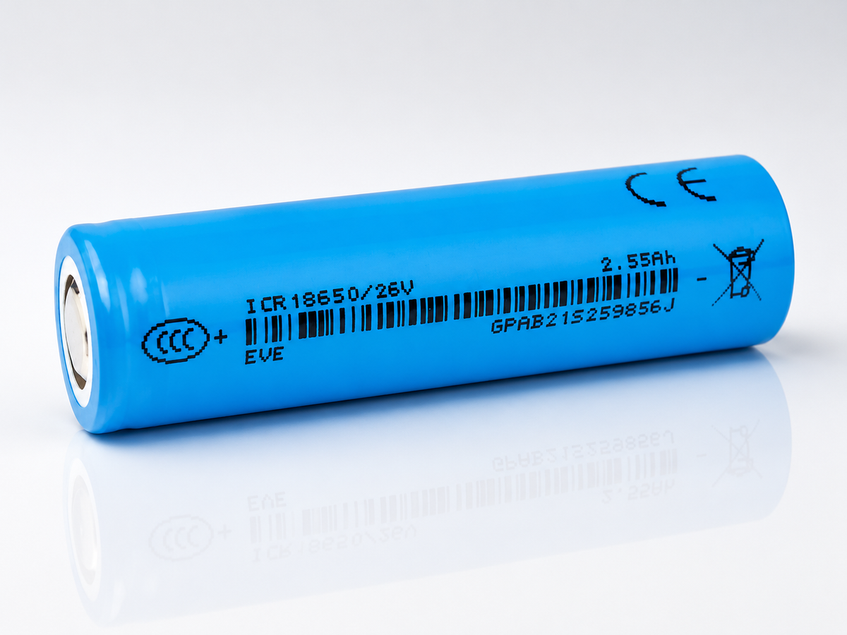
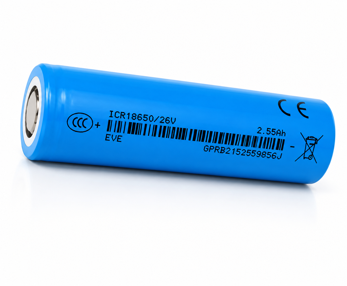


KEY SPECS · EVE ENERGY ICR18650/26V
SOURCE [1]- SIZE
- Ø18.35 × 65.00 mm
- nominal ±0.10 / ±0.15 · with tube
- CAPACITY
- 2,550 mAh typ.
- 2,500 mAh min.
- 0.5 A to 2.50 V
- CURRENT
- Not stated by manufacturer
- continuous discharge
- TEMPERATURE
- −20 to 60 °C
- discharge · cell surface
- charge 0 to 45 °C · cell surface
[1] Product Specification, Lithium-ion rechargeable cell, Model EVE-ICR18650/26V, Version No. B, on file since 2021-05-12
EVE · 18650 · ICR18650/26V
An 18650 lithium-ion cell from EVE, 3.60 V typical: 2,550 mAh typical and 2,500 mAh minimum, discharged at 0.5 A to 2.50 V after a 0.5 A, 4.20 V CC-CV charge to 50 mA [1] §3.1–§3.3, and 2,400 mAh minimum at 2.5 A (§3.2). EVE’s current specification prints no continuous or maximum discharge rating; section 03 explains the 7.5 A figures it does print. Below: every figure with its condition and its section in the specification, the percentages EVE’s tables print, what changed from the older edition, and our arithmetic with its formula. The specification isn’t posted (EVE marks it confidential), so call or text us to check a figure against it.
CAPACITY, TYPICAL2,550 mAh2,500 mAh minimum; 0.5 A to 2.50 V after a 0.5 A, 4.20 V charge [1] §3.1, §3.2
MINIMUM AT 2.5 A2,400 mAh“Discharge: 2.5A, 2.50V DC cut-off” [1] §3.2
CONTINUOUS DISCHARGENot stated by manufacturer[1] prints no continuous or maximum discharge rating; its only discharge maximum (§3.7) is instantaneous (section 03)
CHARGE LIMIT≤ 1.25 Aat 15 to 45 °C cell surface; ≤ 0.5 A from 0 to 15 °C [1] §3.11
ENERGY9.18 Whprinted in the SDS and UN38.3 documents [3]–[5]; check: 3.60 V × 2.550 Ah, calculated from [1]
CELL WEIGHT48.0 g“48.0g Max” [1] §3.9
SDS [3] and UN38.3 test summary [5], PDFs from Pony Testing Group Shenzhen Co., Ltd., both dated 2021-04-25. The full UN38.3 report [4], MPI5V1NC50842721a, isn’t posted on our store, so we cite it by number, lab and date. EVE’s specification [1] is quoted here but not linked: EVE marks every page confidential.
A bare cell: a component for protected packs and devices built for it. Not for vaping. Charge on a lithium-ion (Li-ion) charger that stops at 4.20 V.
01SPEC PLATE
Every figure, with its condition.
EVE’s data sheet for the 26V is a 16-page product specification [1]; this page calls it the specification. EVE marks every page confidential, so we quote it and don’t link it. We hold two editions; this page follows the newer one, Version No. B (January, 2021), and calls it the current edition. Section 08 shows what changed from the older edition [2]. The current edition’s figures come first, copied as printed. Then the percentages its tables print, our arithmetic, and facts from the safety data sheet (SDS) [3] and the UN38.3 transport test report [4] and summary [5], issued by a testing lab. Each row names its source or shows its formula.
| SPECIFICATION | VALUE | CONDITION · SOURCE |
|---|---|---|
| AS PRINTED · MANUFACTURER copied from the current specification [1] | ||
| MODEL | ICR18650/26V | page header [1]; model name “EVE-ICR18650/26V” [1] §2.2; the SDS, the UN38.3 report, its summary and the sleeve in their photos print “ICR18650/26V” [3]–[5] (fig 1.5) |
| CAPACITY, TYPICAL | 2,550 mAh | “3.1 Typical Discharge Capacity”; “Charge: 0.5A, 4.20V, CCCV 50mA cut-off” / “Discharge: 0.5A, 2.50V DC cut-off” [1] §3.1 |
| CAPACITY, MINIMUM | 2,500 mAh | “3.2 Min. Discharge Capacity”, the same charge and discharge [1] §3.2; “Discharge Capacity ≥ 2500mAh” at a “discharge current of 0.5A (0.2C) with 2.50V cut-off at 25°C within 1 hour after the standard charge” §7.3 |
| CAPACITY, MINIMUM AT 2.5 A | 2,400 mAh | “2400mAh”, “Discharge: 2.5A, 2.50V DC cut-off” after the same charge [1] §3.2; repeated as “Minimum Capacity” in §13.2 |
| TYPICAL VOLTAGE | 3.60 V | “3.3 Typical Voltage”, as printed, in the table headed “3.0. Nominal Specifications”; no row is named nominal voltage [1] §3.3 |
| CHARGE VOLTAGE | 4.20 ± 0.05 V | “4.20±0.05V”, CC-CV (constant current, then constant voltage), in “3.4 Standard Charge” and “3.5 Rapid Charge” [1] §3.4, §3.5 |
| DISCHARGE CUT-OFF | 2.50 V | “2.50V cut-off” in “3.6 Standard Discharge”; range “4.20~2.50V”, the “Charge/Discharge Voltage Range” [1] §3.6, §3.8 |
| 1C | 2.5 A | “2.5A (1C)” in the §9.1 overcharge test, a test condition; “0.5A (0.2C)” (§7.1) and “1.25A (0.5C)” (§7.2) are on the same basis; §9.3 alone prints “2.8A (1C)” [1] |
| STANDARD CHARGE | 0.5 A | “CCCV, 0.5A, 4.20±0.05V, 50mA cut-off” [1] §3.4; “charge current 0.5A (0.2C)” “at 25°C for capacity”, §7.1 |
| RAPID CHARGE | 1.25 A | “CCCV, 1.25A, 4.20±0.05V, 50mA cut-off” [1] §3.5; “charge current 1.25A (0.5C)” “at 25°C”, §7.2 |
| CHARGE, 15 TO 45 °C | ≤ 1.25 A | “≤1.25A” at “Charge: 15 to 45 °C”, under “3.11 Operation Temperature (Surface Temperature)” [1] §3.11 |
| CHARGE, 0 TO 15 °C | ≤ 0.5 A | “≤0.5A” at “Charge: 0 to 15 °C”, cell surface [1] §3.11; no charge range below 0 °C or above 45 °C |
| STANDARD DISCHARGE | 0.5 A | “DC, 0.5A, 2.50V cut-off” [1] §3.6 |
| CONTINUOUS DISCHARGE | Not stated by manufacturer | [1] prints no continuous or maximum discharge rating. Its only discharge maximum, “3.7 Max. Instantaneous Discharge”, is an instantaneous figure printed with no duration: kept off this plate and every chart (section 03) |
| DISCHARGE TEMPERATURE | −20 to 60 °C | “Discharge: -20 to 60°C(Pack cut-off temperature 70°C)”, cell surface [1] §3.11 |
| STORAGE TEMPERATURE | 0–25 °C | “1 year” “0~25°C”, “3 months” “0~45°C”, “1 month” “0~60°C”, “(At Shipping SOC)” [1] §3.12 |
| AC IMPEDANCE | ≤ 30 mΩ | “Initial Internal Impedance ≤ 30mΩ”, “at AC 1kHz at shipping SOC” [1] §7.4 |
| CYCLE LIFE | ≥ 70 % Ci | after 1,000 cycles of “Charge: standard charge (1.25A, 4.20V, 125mA cut-off).” “Discharge: standard discharge (2.50A, 3.00V cut-off).” “Rest time: 10min after charge and 30min after discharge.”; §7.7 calls this 1.25 A charge and 2.50 A discharge “standard”, though §3.4 and §3.6 set the standard charge and discharge at 0.5 A; Ci: “the first discharge capacity of cycle life test at 25±2°C” [1] §7.7 (fig 6.1) |
| SHIPPING VOLTAGE | 3.600–3.650 V | “3.600V to 3.650V” “(35~45% SOC)” [1] §7.9, §13.2 |
| CELL WEIGHT | 48.0 g | “48.0g Max”: a maximum; no typical weight printed [1] §3.9 |
| HEIGHT | 65.00 ± 0.15 mm | “Height: 65.00±0.15mm” [1] §3.10, “with tube” Fig. 1 |
| DIAMETER | 18.35 ± 0.10 mm | “Diameter: 18.35±0.10mm” [1] §3.10, “with tube” Fig. 1 |
| TEST CONDITIONS | 25 ± 2 °C | humidity “under 65% RH”, for every test in [1] “Unless otherwise specified” §6.1 |
| + Source: [1] EVE Energy Co., Ltd., PRODUCT SPECIFICATION, Lithium-ion rechargeable cell, Model: EVE-ICR18650/26V, Spec. No. RD-EVE ICR18650/26V-S121-LF, Version No. B, January, 2021 (as printed; our copy’s file name reads S118, every page prints S121; its revision history dates revision B 2021-01-25; 16 pages); on file; not linked, as EVE marks every page “-EVE Energy CO., LTD Confidential Proprietary-”. Call or text us with questions about its figures. | ||
| SPECIFICATION | VALUE | CONDITION · SOURCE |
|---|---|---|
| PRINTED IN THE SPECIFICATION’S TABLES percentages against their own printed basis (no mAh conversion) and the §13.2 sorting limits [1] | ||
| RATE TEST AT 7.5 A (3C) | ≥ 90 % | “7.5A (3C)” “≥90%”, “2.50V cut-off after the standard charge”; “Relative capacity is divided by the discharge capacity of 0.5A.” A test current, not a rating [1] §7.5 (section 03) |
| DISCHARGE AT −20 °C | ≥ 70 % | “with discharge constant current 0.5A (0.2C) and 2.50V cut-off after the standard charge at 25°C”, “after 3 hours storage at the test environment”; “Relative capacity is divided by the 0.5A discharge capacity at 25°C.” [1] §7.6 |
| DISCHARGE AT 55 °C | ≥ 90 % | the same basis [1] §7.6 |
| RETENTION, 28 DAYS AT 25 °C | ≥ 85 % | retention “≥85%”, recovery “≥90%”, each “after fully standard charged storage”, against the “Initial Capacity: Standard discharge capacity.” [1] §7.8 |
| RETENTION, 7 DAYS AT 55 °C | ≥ 85 % | recovery ≥ 90 % [1] §7.8 |
| RECOVERY, 28 DAYS AT 45 °C | ≥ 90 % | retention printed “/” [1] §7.8 |
| VARIATION OF CAPACITY | ≤ 40 mAh | voltage “≤10mV”, AC impedance “≤3mΩ”; the group of cells is not stated [1] §13.2 |
| CALCULATED arithmetic on [1], shown so you can check it | ||
| ENERGY, CHECK | 9.18 Wh | 3.60 V Typical Voltage × 2.550 Ah typical [1] §3.3, §3.1; equals the Wh printed in [3]–[5]; [1] prints no Wh |
| RUNTIME AT 0.5 A | ≥ 5 h 00 min | 2,500 mAh minimum ÷ 0.5 A [1] §3.2; about 5 h 06 min at the 2,550 mAh typical |
| RUNTIME AT 2.5 A | ≥ 57.6 min | 2,400 mAh minimum at 2.5 A ÷ 2.5 A [1] §3.2 |
| CHARGE LIMIT, 0 TO 15 °C, AS C-RATE | 0.2C | 0.5 A ÷ 2.5 A; at 15 to 45 °C, 1.25 A ÷ 2.5 A = 0.5C, the printed “1.25A (0.5C)” [1] §3.11, §7.2 |
| CYCLE-LIFE TEST AS C-RATES | 0.5C · 1C | 1.25 A charge and 2.50 A discharge ÷ 2.5 A [1] §7.7; not printed as C-rates |
| CHARGE CUT-OFFS AS C-RATE | 0.02C · 0.05C | 50 mA ÷ 2,500 mA [1] §3.4, §3.5; 125 mA ÷ 2,500 mA, the §7.7 cycle-life charge |
| SIZE LIMITS | 64.85–65.15 mm | height, from 65.00 ± 0.15 mm; diameter 18.25–18.45 mm, from 18.35 ± 0.10 mm [1] §3.10 |
| VOLUME | 17.19 cm³ | π ÷ 4 × 18.35² × 65.00 mm³ at the printed size [1] §3.10; 16.96–17.42 cm³ across the tolerances |
| FROM THE SAFETY DATA SHEET (SDS) AND UN38.3 DOCUMENTS copied as printed from [3], [4] and [5] | ||
| MODEL | ICR18650/26V | the sample model in [3], [4] and [5], and on the sleeve in the photos in [4][5] (fig 1.5) |
| FIGURES · SDS | 3.6 V · 2,550 mAh | “Voltage” “3.6V”, “Electric capacity” “2550mAh” [3] Section 9; no typical, nominal or minimum and no condition printed |
| ENERGY | 9.18 Wh | “Electric Energy” “9.18Wh” [3] Section 9; “(3.6V 2550mAh 9.18Wh)” on the cover of [4]; “Watt-hour rating” “9.18Wh” [5]; no condition printed; [1] prints no Wh (our check, under CALCULATED above) |
| CATHODE | “cobalt lithium manganese nickel oxide” | CAS 346417-97-8, “≤45” under “Weight (%)” [3] Section 3; [1] names no cathode |
| TRANSPORT | UN3480 | “UN3480”, Class “9” (IATA), and “According to the Packing Instruction 965 section IB of IATA DGR 62nd Edition for transportation, Cargo aircraft only.” [3] Section 14, dated 2021-04-25 |
| UN38.3 REPORT | MPI5V1NC |
T.1–T.6 and T.8 “PASS”; T.7 “Not applicable”; Pony Testing Group Shenzhen Co., Ltd., issue date 2021-04-25 [4]; not posted (section 07) |
| UN38.3 SUMMARY | MPI5V1NC |
issue date 2021-04-25, linked [5] |
| SAFETY DATA SHEET | MPI5V1NC |
Date 2021-04-25; no version or validity printed; linked [3] |
| + Source: [1] EVE Energy Co., Ltd., PRODUCT SPECIFICATION, Lithium-ion rechargeable cell, Model: EVE-ICR18650/26V, Spec. No. RD-EVE ICR18650/26V-S121-LF, Version No. B, January, 2021 (as printed; our copy’s file name reads S118, every page prints S121; its revision history dates revision B 2021-01-25; 16 pages); on file; not linked, as EVE marks every page “-EVE Energy CO., LTD Confidential Proprietary-”. Call or text us with questions about its figures. + Source: [3] Pony Testing International Group (Pony Testing Group Shenzhen Co., Ltd.), “MSDS Report”, Material Safety Data Sheet, Report No. MPI5V1NC50848716a, “Rechargeable Li-ion Cell” “ICR18650/26V”, applicant “EVE Energy Co.,Ltd.”; Date 2021-04-25 (as printed; no version or validity printed; it replaces report MPI5V1NC50848716) · SDS PDF + Source: [4] Pony Testing Group Shenzhen Co., Ltd. (CNAS L3192), UN38.3 Test Report, Report ID MPI5V1NC50842721a, “Rechargeable Li-ion Cell”, model “ICR18650/26V”, Manual of Tests and Criteria (ST/SG/AC.10/11/Rev.7 Part III sub-section 38.3); entrust date 2021-03-25, finished date 2021-04-09, issue date 2021-04-25 (as printed; no version or validity printed; it replaces report MPI5V1NC50842721); applicant “EVE Energy Co.,Ltd.”, manufacturer “EVE Hyperpower Lithium Batteries Inc.”; on file; not posted on our store, so cited by number, lab and date + Source: [5] Pony Testing Group Shenzhen Co., Ltd., Lithium Cell or Battery UN38.3 Test Summary, Report ID MPI5V1NC50843749a, for report MPI5V1NC50842721a; issue date 2021-04-25 (as printed; no version or validity printed) · UN38.3 summary PDF | ||
PRINTED IN [1]FIG 1.1
Voltage window
2.50 V3.60 V4.20 Vcut-offtypicalcharge
Black marks: voltages printed in [1]: the “2.50V cut-off” of the standard discharge (§3.6), the Typical Voltage “3.60V” (§3.3) and the charge voltage “4.20±0.05V” (§3.4). Orange band: the shipping range, “3.600V to 3.650V” “(35~45% SOC)” [1] §7.9.
PRINTED IN [1]FIG 1.2
Currents, as printed
Standard discharge “DC, 0.5A, 2.50V cut-off” [1] §3.6
0.5 A
Minimum-capacity test discharge “Discharge: 2.5A, 2.50V DC cut-off”, for the “2400mAh” minimum [1] §3.2; a test condition
2.5 A
Cycle-life test discharge “Discharge: standard discharge (2.50A, 3.00V cut-off).” [1] §7.7; a test condition
2.5 A
Continuous discharge Not stated by manufacturer: [1] prints no continuous or maximum discharge rating
Standard charge “CCCV, 0.5A, 4.20±0.05V, 50mA cut-off” [1] §3.4
0.5 A
Rapid charge “CCCV, 1.25A, 4.20±0.05V, 50mA cut-off” [1] §3.5
1.25 A
Charge limit, 15 to 45 °C “≤1.25A”, cell surface [1] §3.11
1.25 A
Charge limit, 0 to 15 °C “≤0.5A”, cell surface [1] §3.11
0.5 A
Currents as printed in [1], each with its condition, in amps. Orange: the §3.11 charge-current limits at the cell surface, the only charge-current limits [1] prints. Gray: the discharge currents of two tests, §3.2’s minimum capacity and §7.7’s cycle life; test conditions, not ratings. [1] prints no continuous, maximum or pulse discharge rating; its §3.7 figure is instantaneous, with no duration printed, so it is kept off this chart (section 03).
PRINTED IN [1]FIG 1.3
Temperature ranges, as printed
Discharge “Discharge: -20 to 60°C(Pack cut-off temperature 70°C)”, cell surface [1] §3.11
Charge, at most 1.25 A “Charge: 15 to 45 °C”, “≤1.25A” [1] §3.11
Charge, at most 0.5 A “Charge: 0 to 15 °C”, “≤0.5A” [1] §3.11
Storage, 1 year “0~25°C” at shipping SOC [1] §3.12
Pack cut-off “(Pack cut-off temperature 70°C)”, printed in the discharge row: a pack figure, not a cell rating [1] §3.11
Table 7.6 test points −20, 25 and 55 °C, test environment [1] §7.6
Charge and discharge rows: cell surface, “(Surface Temperature)” [1] §3.11. Orange: charging, in two bands with different current limits that share 15 °C as printed. Storage row: the §3.12 range for 1 year at shipping SOC; fig 6.3 has all three. Last row: table 7.6’s test-environment temperatures (“after 3 hours storage at the test environment”), not cell-surface readings; section 04 below. [1] prints no ambient charge or discharge range.
DOCUMENTS · [1][3]–[5]FIG 1.4
Capacity, as each document prints it
Typical, [1] §3.1 “2550mAh”, “Discharge: 0.5A, 2.50V DC cut-off”
2,550
Minimum, [1] §3.2 “2500mAh”, the same charge and discharge
2,500
Minimum at 2.5 A, [1] §3.2 “2400mAh”, “Discharge: 2.5A, 2.50V DC cut-off”
2,400
SDS [3] “Electric capacity” “2550mAh”; no typical, nominal or minimum, no condition
2,550
UN38.3 report [4] “Rated capacity” “2550mAh” in its sample description; no condition
2,550
UN38.3 summary [5] “Sample parameter” “3.6V 2550mAh”; no condition
2,550
Sleeve, in the photos in [4][5] “2.55Ah”
2,550
Each document’s capacity figure, as printed, on a 2,300–2,650 mAh scale; the axis doesn’t start at zero. [1] labels 2,550 mAh Typical and prints two minimums, 2,500 mAh at 0.5 A and 2,400 mAh at 2.5 A, each to 2.50 V after “Charge: 0.5A, 4.20V, CCCV 50mA cut-off”. [3]–[5] print “2550mAh” and the sleeve “2.55Ah”, each without a condition; [4] labels it “Rated capacity”. Plan on the minimum for your current.
DOCUMENTS · [1]–[5]FIG 1.5
Model name, as each document prints it
| WHERE | AS PRINTED |
|---|---|
| [1] page header; Fig. 1 | “ICR18650/26V” |
| [1] cover; §2.2 Model name | “EVE-ICR18650/26V” |
| [3] Sample Model | “ICR18650/26V” |
| [4] Sample model | “ICR18650/26V” |
| [5] Sample model | “ICR18650/26V” |
| Sleeve, in the photos in [4][5] | “ICR18650/26V” |
Every document prints the model “ICR18650/26V”; [1]’s cover and §2.2 print it as “EVE-ICR18650/26V”. Only the older edition defines its letters: “The letter "ICR" defines Cylindrical Li-ion rechargeable cell” [2] §2.3. The definition names no cathode material; the SDS lists the cathode as “cobalt lithium manganese nickel oxide” [3] Section 3. “26V” is part of the model name, not a voltage: the cell’s voltage is the Typical Voltage, “3.60V” [1] §3.3.
PRINTED IN [1]FIG 1.6
Sorting limits, as printed
| ITEM | SPEC. | REMARK |
|---|---|---|
| Minimum Capacity | 2400mAh | Charge: 0.5A, 4.20V, CCCV 50mA cut-off Discharge: 2.5A, 2.50V DC cut-off |
| Shipping Voltage | 3.600V to 3.650V | 35~45% SOC |
| Variation of Capacity | ≤40mAh | / |
| Variation of Voltage | ≤10mV | / |
| Variation of AC Impedance | ≤3mΩ | / |
Table 13.2 of [1], Sorting, copied as printed. It doesn’t say over which group of cells the variations apply, and it defines no grades. A guide when you match cells for a pack.
02 · CAPACITY
At 2.5 A, 2,400 mAh minimum.
EVE’s specification prints two minimum capacities for the 26V, each after the same charge, “Charge: 0.5A, 4.20V, CCCV 50mA cut-off”: “2500mAh” discharged at 0.5 A and “2400mAh” at 2.5 A, both to 2.50 V [1] §3.2. The typical, 2,550 mAh, is at 0.5 A (§3.1). 2.5 A is 1C on the basis [1] prints, “2.5A (1C)” (§9.1). At higher currents [1] prints only a percentage, in table 7.5 (section 03).
0.5 A · 0.2C2,500 mAhminimum; 2,550 mAh typical [1] §3.1, §3.2
2.5 A · 1C2,400 mAhminimum, to 2.50 V [1] §3.2; repeated in §13.2
PRINTED IN [1]FIG 2.1
mAh
2,3502,4002,4502,5002,5502,60000.511.522.532,550 typical2,500 minimum2,400 minimum
Discharge current, A
Data: [1] §3.1 and §3.2, in the table headed “3.0. Nominal Specifications” · each after “Charge: 0.5A, 4.20V, CCCV 50mA cut-off” · discharged at 0.5 A or 2.5 A to 2.50 V · minimums and the typical as printed · the points stand alone: EVE prints no curve between them · no temperature in §3; §6.1 sets “25±2°C” “Unless otherwise specified” · axis starts at 2,350 mAh · values in the spec plate
03BY CURRENT
Capacity, by current.
Table 7.5 of [1] prints the capacity at 0.5 A and at a 7.5 A (3C) test current, as a percent of the capacity at 0.5 A. It prints no mAh at 7.5 A, so this page doesn’t convert it. The C-rates use the 1C of [1], 2.5 A.
PRINTED IN [1]FIG 3.1
Relative capacity, by current
Table 7.5 of [1]: capacity at each current, “2.50V cut-off after the standard charge”, as a percent: “Relative capacity is divided by the discharge capacity of 0.5A.” A ≥ figure is a minimum. [1] prints no mAh and no temperature here (§6.1’s “25±2°C” applies “Unless otherwise specified”). Gray: “7.5A (3C)”, a test current with a pass threshold, not a discharge rating.
DATA TABLE · FIG 3.1
| CURRENT | RELATIVE CAPACITY |
|---|---|
| 0.5A (0.2C) | 100% |
| 7.5A (3C) | ≥90% |
PRINTED IN [1] + CALCULATEDFIG 3.2
Currents on the 1C basis
Standard charge and discharge “0.5A (0.2C)” [1] §7.1, §7.3
0.2C
Rapid charge “1.25A (0.5C)” [1] §7.2; the same current as the §3.11 limit at 15 to 45 °C
0.5C
Minimum-capacity test “Discharge: 2.5A, 2.50V DC cut-off” [1] §3.2: 2.5 A ÷ 2.5 A, our arithmetic
1C
Cycle-life test 1.25 A charge, 2.50 A discharge [1] §7.7: 0.5C and 1C, our arithmetic
1C
Overcharge test “2.5A (1C)” [1] §9.1, a test condition
Table 7.5 test currents “0.5A (0.2C)” and “7.5A (3C)” [1] §7.5
Four of the five C-rates [1] prints with amps share one basis, 1C = 2.5 A (§7.1, §7.2, §7.5, §9.1), numerically the 2,500 mAh minimum capacity; [1] doesn’t say which capacity defines C. The rows marked our arithmetic use that basis. §9.3 alone prints “2.8A (1C)”; it is quoted as printed and not charted. Gray: test discharges. [1] rates no discharge current, so no row here is a discharge rating.
Why there’s no “7.5A” rating
- EVE’s current specification [1] prints 7.5 A only as “3.7 Max. Instantaneous Discharge” “DC, 7.5A, 2.50V cut-off” (§3.7), an instantaneous figure printed with no duration, and as “7.5A (3C)”, a test current in table 7.5 (fig 3.1). Neither is a rating for a steady load.
- So [1] prints no continuous or maximum discharge rating, and this page shows none: the instantaneous figure stays off the spec plate and every chart.
- The highest current with a printed minimum capacity is 2.5 A: 2,400 mAh, “Discharge: 2.5A, 2.50V DC cut-off” [1] §3.2. EVE’s cycle-life test discharges at 2.50 A to 3.00 V (§7.7). Both are test conditions, not ratings.
- EVE’s older edition called its discharge figure continuous; the current edition dropped that rating without saying why. This page follows the current edition (section 08).
- A handling clause, [1] §12.3.1, reads: “The cell shall be discharged continuously at less than maximum discharging current specified in the specification. In case of the higher discharging current should be set, it shall be discussed with EVE.” [1] prints no current by that name; the clause names no figure and is not a rating.
- If your device needs a rated continuous current, choose a cell whose document prints one (section 09), or call or text us.
04TEMPERATURE
Capacity in the cold and the heat.
Table 7.6 of [1] prints the capacity at −20, 25 and 55 °C, discharged at 0.5 A (0.2C) after a standard charge at 25 °C and 3 h at the test temperature, as a percent of the 25 °C figure. At −20 °C, the coldest test environment in the table, it prints ≥ 70 %; §3.11 allows discharge down to −20 °C at the cell surface.
PRINTED IN [1]FIG 4.1
Relative capacity, by discharge temperature
Capacity when the discharge runs at each temperature, “with discharge constant current 0.5A (0.2C) and 2.50V cut-off after the standard charge at 25°C”, “after 3 hours storage at the test environment”. Printed in table 7.6 of [1] as a percent: “Relative capacity is divided by the 0.5A discharge capacity at 25°C.” Each ≥ figure is a minimum. Orange: −20 °C, the coldest test temperature in table 7.6.
DATA TABLE · FIG 4.1
| TEMPERATURE | RELATIVE CAPACITY |
|---|---|
| -20°C | ≥70% |
| 25°C | 100% |
| 55°C | ≥90% |
PRINTED IN [1]FIG 4.2
Discharge temperature, range and table
Discharge “Discharge: -20 to 60°C(Pack cut-off temperature 70°C)”, cell surface [1] §3.11
Table 7.6 points −20, 25 and 55 °C test environment: ≥ 70 %, 100 %, ≥ 90 % [1] §7.6
Charge “≤0.5A” at 0 to 15 °C and “≤1.25A” at 15 to 45 °C, cell surface [1] §3.11 (fig 5.1)
Test condition “25±2°C”, “Unless otherwise specified” [1] §6.1
The discharge range and charge bands are cell-surface temperatures, as [1] §3.11 prints them. The table 7.6 points are test-environment temperatures (3 h at each), and gray marks §6.1’s test condition, “25±2°C”: neither is a cell-surface reading. The cell may discharge from −20 °C but not charge below 0 °C at the cell surface (orange; the tick at 15 °C divides the two charge bands). [1] prints no ambient charge or discharge range.
05CHARGING
Charging: 0.5 A standard, 1.25 A rapid.
The specification prints two charges, both CC-CV (constant current, then constant voltage) to “4.20±0.05V” with a 50 mA cut-off: a 0.5 A standard charge and a 1.25 A rapid charge [1] §3.4, §3.5. It limits the charge current by cell surface temperature (§3.11) and prints no charge time.
PRINTED IN [1]FIG 5.1
Charge-current limit, by cell surface temperature
A
00.51.01.5−20015254560≤ 0.5 A≤ 1.25 AStandardRapidnone
printed
Cell surface temperature, °C
printed
The charge-current limit [1] §3.11 prints for each band of cell surface temperature: “≤0.5A” at “Charge: 0 to 15 °C” and “≤1.25A” at “Charge: 15 to 45 °C”; the bands share 15 °C as printed. [1] prints no charge range outside 0 to 45 °C. Points: the Standard Charge, 0.5 A (0.2C), and the Rapid Charge, 1.25 A (0.5C), defined “at 25°C” [1] §7.1, §7.2, a test temperature, not a cell-surface reading; drawn at 25 °C for reference. From 0 to 15 °C the limit equals the standard charge, so charge at 0.5 A or less there; the 1.25 A rapid charge is above it.
DATA TABLE · FIG 5.1
| TEMPERATURE | CHARGE CURRENT, AS PRINTED |
|---|---|
| Charge: 0 to 15 °C, cell surface | ≤0.5A |
| Charge: 15 to 45 °C, cell surface | ≤1.25A |
| Standard Charge, at 25 °C, a test temperature | CCCV, 0.5A, 4.20±0.05V, 50mA cut-off |
| Rapid Charge, at 25 °C, a test temperature | CCCV, 1.25A, 4.20±0.05V, 50mA cut-off |
PRINTED IN [1]FIG 5.2
Voltage thresholds, as printed
Working range “4.20~2.50V” [1] §3.8
Charge voltage “4.20±0.05V”, CC-CV [1] §3.4, §3.5
Discharge cut-off “2.50V cut-off” [1] §3.6
Shipping voltage “3.600V to 3.650V”, “(35~45% SOC)” [1] §7.9, §13.2
Long-term storage “from 3.50V to 3.80V”, “3 months or more” [1] §13.1
Cycle-life test cut-off “3.00V cut-off” [1] §7.7
Voltages as printed in [1]. Orange: the working range. A pack’s battery management system (BMS) should keep each cell inside it: [1] §12.3.3 asks for “a device to prevent further discharging exceeding discharging cut-off voltage”. The scale starts at 2.0 V.
Before you charge
- Use a lithium-ion charger with a CC-CV profile that stops at 4.20 V: [1] prints “4.20±0.05V” (§3.4).
- Standard charge: “CCCV, 0.5A, 4.20±0.05V, 50mA cut-off” [1] §3.4. Rapid charge: “CCCV, 1.25A, 4.20±0.05V, 50mA cut-off” §3.5; the cycle-life test (§7.7) also charges at 1.25 A. [1] prints no charge time and no charge current above 1.25 A outside its §9.1 overcharge test (“2.5A (1C)”, a test condition).
- At the cell surface: “≤1.25A” at “Charge: 15 to 45 °C”, and “≤0.5A” at “Charge: 0 to 15 °C” [1] §3.11. Below 0 °C or above 45 °C, don’t charge.
- Never charge in reverse: “Inverse charging shall be strictly prohibited.” [1] §12.2.4.
- In a pack, a battery management system (BMS) should end charge at 4.20 V per cell and stop on temperature; [1] §12.6.6 asks for a device to “monitor each voltage of cell block”.
EVE draws no chart of the charge bands: fig 5.1 plots the table of [1] §3.11, and fig 5.2 sets the voltages [1] prints on one scale.
06CYCLE LIFE AND STORAGE
What it keeps after use and storage.
[1] sets at least 70 % of Ci, the capacity of the test’s own first discharge, after 1,000 cycles, and prints the capacity kept after storage at 25 and 55 °C, and the capacity recovered at 25, 45 and 55 °C. It prints no cycle-life curve, so the charts show only its printed points.
PRINTED IN [1]FIG 6.1
Cycle life, as printed
The cycle-life clause of [1] §7.7, as printed: “Charge: standard charge (1.25A, 4.20V, 125mA cut-off).” “Discharge: standard discharge (2.50A, 3.00V cut-off).” “Rest time: 10min after charge and 30min after discharge.” “Capacity after 1000 cycles.” “Capacity≥70% Ci (Ci : the first discharge capacity of cycle life test at 25±2°C)”. §7.7 calls this 1.25 A charge and 2.50 A discharge “standard”, although §3.4 and §3.6 set the standard charge and discharge at 0.5 A. 70 % is of Ci, the test’s own first discharge, not of the 2,550 mAh typical or 2,500 mAh minimum, and each discharge stops at 3.00 V, not 2.50 V. Orange: after 1,000 cycles. A criterion, not a curve: [1] prints no capacity between the first cycle and cycle 1,000.
PRINTED IN [1]FIG 6.2
Retention and recovery after storage
Retention: the first discharge after storageRecovery, in gray figures: after three cycles
Capacity after storage at each temperature and time, “after fully standard charged storage”, as a percent of the “Initial Capacity: Standard discharge capacity.” [1] §7.8: “Retention Ratio= Retention Capacity/ Initial Capacity*100%”, “Recovery Ratio= Recovery Capacity/ Initial Capacity*100%”. Recovery is “The standard discharge capacity of three times cycles after fully standard charged storage”. Each ≥ figure is a minimum; for 28 days at 45 °C, [1] prints “/” for retention, so no bar. [1] §12.4.2: “storage with higher voltage may cause more loss of performance characteristics.”
PRINTED IN [1]FIG 6.3
Storage temperature, by time
1 month “0~60°C” [1] §3.12
3 months “0~45°C” [1] §3.12
1 year “0~25°C” [1] §3.12
3 months or more “normally 0~25°C”, at “from 3.50V to 3.80V” [1] §13.1
Table 7.8 storage tests 25, 45 and 55 °C, fully charged [1] §7.8 (fig 6.2)
Storage temperature by time, as printed in [1] §3.12, “(At Shipping SOC)”: “3.600V to 3.650V” “(35~45% SOC)” (§7.9). For 3 months or more, §13.1 says “it is strongly recommended that the cell is performed one cycle”, with the environment “dry and no corrosive gas”. [1] prints no storage humidity. Orange: the 1-year range, the narrowest. Last row: the temperatures of table 7.8, whose cells were stored fully charged.
07TRANSPORT TESTS
What the UN38.3 report records.
UN38.3 is the set of transport tests for lithium cells and batteries in the UN Manual of Tests and Criteria, Section 38.3. The test report [4] from Pony Testing Group Shenzhen Co., Ltd., issue date 2021-04-25, records “PASS” for T.1 to T.6 and T.8 on the “ICR18650/26V” and “Not applicable” for T.7, with each cell’s readings. It names the applicant “EVE Energy Co.,Ltd.” and the manufacturer “EVE Hyperpower Lithium Batteries Inc.” as printed. The report, MPI5V1NC50842721a, isn’t posted on our store, so we cite it by number, lab and date; its summary [5], MPI5V1NC50843749a, is linked, and under “Physical description” describes its samples as “Blue Cylindrical”. The lab’s samples, not our lot.
PRINTED IN [4]FIG 7.1
Peak temperature of each cell, T.5 and T.6
T.5 External short circuit, N1–N5 and C1–C5T.6 Impact, N6–N10 and C6–C10
°C
9095100105110N1–N5C1–C5N6–N10C6–C10N5 “03.8”
as printed
Cell, as numbered in [4]
as printed
Each cell’s “Peak temperature (℃)” in [4], as printed. T.5: N1–N5 (“Cells at first cycle in fully charged states”) and C1–C5 (“Cells after 25 cycles ending in fully charged states”), the cells that ran T.1 to T.4 (fig 7.2). T.6: N6–N10 and C6–C10, “at 50% of the design rated capacity”. N5: “03.8”, as printed; not plotted. Nine other T.5 cells: 101.3–107.0 °C; T.6: 93.2–99.4 °C (our ranges). T.5’s criterion: “Cells and batteries meet this requirement if their external temperature does not exceed 170℃ and there is no disassembly, no rupture and no fire during the test and within six hours after the test.” [4] prints no T.6 criterion. Every row reads “无 (No)” for disassembly, rupture or fire (T.5) and for disassembly or fire (T.6), and both tests read “PASS”. Axis from 90 °C. The lab’s samples, not our lot.
DATA TABLE · FIG 7.1 · T.5
| T.5 CELL | PEAK °C |
|---|---|
| N1 | 101.3 |
| N2 | 103.2 |
| N3 | 104.2 |
| N4 | 106.5 |
| N5 | “03.8”, as printed |
| C1 | 105.1 |
| C2 | 107.0 |
| C3 | 103.9 |
| C4 | 103.4 |
| C5 | 106.2 |
DATA TABLE · FIG 7.1 · T.6
| T.6 CELL | PRE-TEST V | PEAK °C |
|---|---|---|
| N6 | 3.716 | 96.4 |
| N7 | 3.712 | 95.7 |
| N8 | 3.714 | 98.3 |
| N9 | 3.714 | 93.2 |
| N10 | 3.713 | 97.4 |
| C6 | 3.715 | 95.5 |
| C7 | 3.711 | 96.7 |
| C8 | 3.716 | 99.4 |
| C9 | 3.715 | 97.7 |
| C10 | 3.714 | 98.6 |
PRINTED IN [4]FIG 7.2
Voltage loss through T.1–T.4
T.1 Altitude simulation 0.071–0.142 %, our range over the 10 cells in [4]
T.2 Thermal test 2.126–2.221 %, our range over the 10 cells in [4]
T.3 Vibration 0.048–0.097 %, our range over the 10 cells in [4]
T.4 Shock 0.000–0.024 %, our range over the 10 cells in [4]
Each cell’s “Voltage loss (%)” after each test, as printed in [4]: one tick per distinct value; cells with equal values share a tick. The same 10 cells ran T.1 to T.4 in turn, fully charged at 4.237–4.239 V before T.1. The criterion, as printed for T.1: the “open circuit voltage of each test cell or battery after testing is not less than 90% of its voltage immediately prior to this procedure”, a loss of 10 % at most by our arithmetic; every loss here is under 2.3 %. “Mass loss (%)” was 0.004 % or less in every row. [4] records “PASS” for T.1 to T.4. The scale is 0–2.5 %.
DATA TABLE · FIG 7.2
| CELL | T.1 % | T.2 % | T.3 % | T.4 % |
|---|---|---|---|---|
| N1 | 0.118 | 2.173 | 0.072 | 0.000 |
| N2 | 0.118 | 2.197 | 0.072 | 0.000 |
| N3 | 0.142 | 2.174 | 0.048 | 0.024 |
| N4 | 0.094 | 2.221 | 0.048 | 0.000 |
| N5 | 0.118 | 2.126 | 0.097 | 0.024 |
| C1 | 0.118 | 2.173 | 0.072 | 0.000 |
| C2 | 0.094 | 2.173 | 0.097 | 0.000 |
| C3 | 0.094 | 2.196 | 0.072 | 0.024 |
| C4 | 0.071 | 2.196 | 0.048 | 0.000 |
| C5 | 0.118 | 2.173 | 0.072 | 0.024 |
PRINTED IN [1][4]FIG 7.3
Mass of the cells the lab weighed
g
45.046.047.048.0N1N2N3N4N5C1C2C3C4C5“48.0g Max” [1] §3.9
Cell, as numbered in [4]
Mass of the 10 cells the lab weighed before T.1, as printed in [4]: 44.954–45.238 g (mean 45.08 g, our arithmetic), below the “48.0g Max” of [1] §3.9 (dotted line). [4]’s sample description and the summary [5] print a mass of “45.02g”. The axis starts at 44.5 g. The lab weighed 10 of the 40 cells it lists (our tally); they are its samples, not our lot.
DATA TABLE · FIG 7.3
| CELL | BEFORE T.1 g | AFTER T.1 | AFTER T.2 | AFTER T.3 | AFTER T.4 |
|---|---|---|---|---|---|
| N1 | 45.238 | 45.238 | 45.238 | 45.238 | 45.238 |
| N2 | 45.042 | 45.042 | 45.042 | 45.042 | 45.042 |
| N3 | 45.180 | 45.179 | 45.177 | 45.177 | 45.176 |
| N4 | 45.083 | 45.082 | 45.080 | 45.080 | 45.080 |
| N5 | 45.069 | 45.069 | 45.069 | 45.067 | 45.067 |
| C1 | 44.954 | 44.954 | 44.953 | 44.953 | 44.952 |
| C2 | 45.008 | 45.007 | 45.005 | 45.003 | 45.003 |
| C3 | 45.080 | 45.079 | 45.078 | 45.076 | 45.076 |
| C4 | 45.108 | 45.108 | 45.108 | 45.106 | 45.106 |
| C5 | 45.074 | 45.074 | 45.072 | 45.072 | 45.071 |
What the report records
| TEST | RESULT | CELLS, AS PRINTED | CONDITION, FROM THE REPORT’S METHOD |
|---|---|---|---|
| T.1 Altitude simulation | “PASS” | “N1~N5 C1~C5”: “Cells at first cycle in fully charged states”; “Cells after 25 cycles ending in fully charged states”; the same cells run T.1 to T.5 in sequence | “stored at a pressure of 11.6kPa or less for at least six hours at ambient temperature (20℃± 5℃)” |
| T.2 Thermal test | “PASS” | the T.1 cells, “N1~N5 C1~C5” | “at a test temperature equal to 72℃± 2℃, followed by storage for at least six hours at a test temperature equal to - 40℃± 2℃”, “10 total cycles” |
| T.3 Vibration | “PASS” | the T.1 cells, “N1~N5 C1~C5” | “a logarithmic sweep between 7Hz and 200Hz and back to 7Hz traversed in 15 minutes”, “repeated 12 times for a total of 3 hours for each of three mutually perpendicular mounting positions of the cell” |
| T.4 Shock | “PASS” | the T.1 cells, “N1~N5 C1~C5” | “a half-sine shock of peak acceleration of 150gn and pulse duration of 6 milliseconds”, “for a total of 18 shocks” |
| T.5 External short circuit | “PASS” | the T.1 cells, “N1~N5 C1~C5” | “57℃±4℃”, then “a total external resistance of less than 0.1 ohm” |
| T.6 Impact | “PASS” | “N6~N10 C6~C10”: “Cells at first cycle at 50% of the design rated capacity”; “Cells after 25 cycles at 50% of the design rated capacity” | “A 9.1kg ± 0.1kg mass is to be dropped from a height of 61 ± 2.5cm” onto a “15.8 ± 0.1mm diameter” bar |
| T.7 Overcharge | “Not applicable” | “---” | — |
| T.8 Forced discharge | “PASS” | “N11~N20 C11~C20”: “Cells at first cycle in fully discharged states”; “Cells after 25 cycles ending in fully discharged states” | “in series with a 12V D.C. power supply at an initial current equal to the maximum discharge current specified by the manufacturer” |
Copied from the test item summary, notes and methods of [4]; cell numbers as printed, counts our tally (40 cells in all). Its conclusion: “The Samples has passed the test items of Manual of Tests and Criteria (ST/SG/AC.10/11/Rev.7), Part III sub-section 38.3.” The summary [5], same lab and date, lists the same results for report MPI5V1NC50842721a. [4] prints no T.8 current or duration. [4]’s sample description also lists declared values, “Maximum continuous charge current” “2500mA”, “Maximum discharge current” “7500mA” and “Limited charge voltage” “4.25V”, none of which the current specification [1] prints as a rating: its highest charge limit is “≤1.25A” at “Charge: 15 to 45 °C” (§3.11) and it prints no continuous discharge rating, so this page follows [1].
EVE’s own test methods
| TEST | EVE’S TEST METHOD, AS PRINTED | PASS CRITERION, AS PRINTED | SECTION |
|---|---|---|---|
| Drop test | “Each fully charged cell is dropped three times from a height of 1.0m onto a concrete floor at 20±5°C. The cells are dropped so as to obtain impacts in random orientations. After the test, the cells shall be put on rest for a minimum one hour and then a visual inspection shall be performed.” | “No fire, no explosion.” | [1] §8.1 |
| Vibration test | “For X and Y axis with cylindrical cell 7Hz→200Hz→7Hz for 15min, repetition 12 times totally 3 hours, the acceleration 1g during 7 to 18Hz, then amplitude 1.6mm and maximum 8g [...]. Tests are to be conducted at 20±5°C.” | “No fire, no explosion, no leakage, with less than 10% of OCV drop.” | [1] §8.2 |
| Overcharge test | “Fully standard discharged cell is charged with 2.5A (1C) to 6.15V”, or for 1 h at most | “No fire, no explosion.” | [1] §9.1 |
| External Short-circuit test | “Fully standard charged cell is to be short-circuited by connecting the positive and negative terminals of the cell with a circuit load having a resistance load of 80±20mΩ. Until the test time is lasting to 10min.” | “No fire, no explosion.” | [1] §9.2 |
| Forced Discharge test | “A fully standard discharged cell is subjected to forced discharge at 2.8A (1C) for 90 min.” (as printed; §9.3 alone pairs 1C with 2.8 A, fig 3.2) | “No fire, no explosion.” | [1] §9.3 |
| Heating test | “To heat up the standard charged cell at heating rate 5°C per minute” to 130 °C and “keep the cell in oven for 30 minutes.” | “No fire, no explosion.” | [1] §9.4 |
| Low Pressure test | “Fully standard charged cell is to be stored at a pressure of 11.6 kPa or less for at least six hours at ambient temperature.” | “No fire, no explosion and no leakage with less than 10% of OCV drop.” | [1] §9.5 |
| Thermal test | “Fully standard charged cell is to be stored for at least 6 hours at a test temperature equal to 75±2°C, followed by storage for at least 6 hours at a test temperature equal to -40±2°C. The maximum time interval between temperatures extreme is 30 minutes. This procedure is to be repeated until 10 total cycles are complete, after which stored for 24 hours at ambient temperature (20±5°C).” | “No fire, no explosion.” | [1] §9.6 |
| Crush Test | “A fully standard charged cell is to be crushed between two flat surfaces. The force for the crushing is to be applied by a hydraulic ram or similar force mechanism. The flat surfaces are to be brought in contact with the cells and the crushing is to be continued until an applied force of 13±1 KN is reached”, then the force is released. | “No fire, no explosion.” | [1] §9.7 |
EVE’s test method and pass criterion for each test in [1] §8 and §9, quoted as printed; [...] marks words left out, and text outside quotation marks is ours. [1] lists them as requirements for the cell and prints no results. It names a standard for each method; naming a standard isn’t a certificate, and we hold none for those standards. On file for transport are the UN38.3 test report [4] and its summary [5]. These are EVE’s requirements, not the tests in [4]: the UN38.3 report ran its own tests on its own samples, with its own conditions (above).
08WHAT CHANGED
The current and older specifications, side by side.
We hold two editions of EVE’s specification. The older one, [2], S116 Edition A (effective 2020.10.29), printed a “Max Continuous Discharge current” of “7500 mA”. The current one, [1], S121 Version No. B (January, 2021), the newest we hold, prints no continuous or maximum discharge rating: its only discharge maximum is printed as “3.7 Max. Instantaneous Discharge” “DC, 7.5A, 2.50V cut-off”, with no duration, and this page keeps it off the spec plate and every chart. EVE removed the continuous rating and doesn’t say why. Every specification figure outside this section comes from [1], not [2].
| ITEM · WHAT CHANGED | CURRENT [1] · S121 VERSION NO. B · JANUARY, 2021 | OLDER EDITION [2] · S116 EDITION A · 2020.10.29 |
|---|---|---|
| Discharge maximum the continuous rating removed; [1]’s 7.5 A maximum is instantaneous, kept off the spec plate and every chart |
“3.7 Max. Instantaneous Discharge” “DC, 7.5A, 2.50V cut-off” §3.7: instantaneous, no duration printed. No continuous or maximum discharge rating | “Max Continuous Discharge current” “7500 mA” §5.12; “Recommended max continuous discharge current is 7500mA.” §12.2.2 |
| Diameter changed; the height is 65.00 ± 0.15 mm in both |
“Diameter: 18.35±0.10mm” §3.10; “18.35±0.10” “with tube” Fig. 1 | “Diameter : Φ18.30±0.15 mm” §5.15; “18.30±0.15mm” Figure A, §3 |
| Cell weight a tolerance became a maximum |
“48.0g Max” §3.9 | “45.0±2.0 g” §5.4 |
| Capacity heading [2]’s heading names 2.75 V, its end-of-discharge voltage 2.5 V; [1] prints 2.50 V |
“Discharge: 0.5A, 2.50V DC cut-off” §3.1, §3.2; range “4.20~2.50V” §3.8 | rows headed “Capacity@4.2~2.75V” §5.1; “End-of-discharge Voltage” “2.5 V” §5.7 |
| Capacity label Nominal became Typical; the same figure |
“Typical Discharge Capacity” “2550mAh” §3.1 | “Nominal Capacity” “2550 mAh”, “Standard charge/discharge” §5.1 |
| Minimum capacity a second minimum at a higher current in both; [2] printed C-rates, [1] prints amps |
“2500mAh” at “Discharge: 0.5A, 2.50V DC cut-off”; “2400mAh” at “Discharge: 2.5A, 2.50V DC cut-off” §3.2 | “Minimum” “2450 mAh” “0.5C discharge”; “2500 mAh” “0.2C discharge” §5.1 |
| AC impedance the limit lowered from 32 to 30 mΩ |
“Initial Internal Impedance ≤ 30mΩ”, “at AC 1kHz at shipping SOC” §7.4 | “AC-IR” “≤32 mΩ”, “AC 1 kHz, (30%~40%)SOC” §5.3 |
| Charge voltage a tolerance added |
“4.20±0.05V” in “3.4 Standard Charge” and “3.5 Rapid Charge” §3.4, §3.5 | “End-of-charge Voltage” “4.2 V” §5.5 |
| Maximum charge current dropped; [1]’s highest charge limit is 1.25 A |
no row named maximum; “≤1.25A” at “Charge: 15 to 45 °C” §3.11; “Rapid Charge” “CCCV, 1.25A, 4.20±0.05V, 50mA cut-off” §3.5 | “Max. Charge current (Not For Cycle)” “2500 mA” §5.10 |
| Charge temperature the table’s upper end from 50 to 45 °C ([2] §12.2.1 already said 0 to 45 °C); the surface-temperature basis added |
“≤0.5A” at “Charge: 0 to 15 °C”, “≤1.25A” at “Charge: 15 to 45 °C”, “(Surface Temperature)” §3.11 | “Charging Temp.” “0~15 °C” “≤500mA”, “15~50 °C” “≤1250mA” §5.13; “Charge the cell in a temperature range of 0°C to 45°C.” §12.2.1 |
| Discharge temperature the same range; the surface basis and a pack cut-off added |
“Discharge: -20 to 60°C(Pack cut-off temperature 70°C)”, “(Surface Temperature)” §3.11 | “Discharging Temp.” “-20~60 °C” §5.13 |
| Storage temperature the lower end from −20 to 0 °C; the humidity dropped |
“1 year” “0~25°C”, “3 months” “0~45°C”, “1 month” “0~60°C”, “(At Shipping SOC)” §3.12; no humidity | “-20~60 °C” “≤1 month”, “-20~45 °C” “≤3 months”, “-20~25 °C” “≤1 year”; “Storage Humidity” “≤70 % RH” §5.13 |
| Long storage a storage voltage added |
“from 3.50V to 3.80V” and “normally 0~25°C” for “3 months or more”, after “one cycle” §13.1 | “Storage the cell at temperature of -20°C ~ 45°C(less than 3 months), low humidity and no corrosive gas atmosphere.” “In case of long period storage (more than 3 months), storage the cell at temperature range of 0°C ~ 25°C, low humidity, no corrosive gas atmosphere.” §12.2.3 |
| Test environment the humidity became an upper limit |
“25±2°C and humidity under 65% RH” §6.1 | “25°C±2°C and humidity 65%±20% RH” §6.1 |
| Standard charge the same current and cut-off; a tolerance added |
“CCCV, 0.5A, 4.20±0.05V, 50mA cut-off” §3.4 | “Standard Charging current” “500 mA” §5.8; “a constant current of 500mA until the voltage is 4.2V, then charged at a constant voltage of 4.2V until its current is less than 50mA” §6.2 |
| Rapid charge the same current; the “not recommended” sentence dropped |
“Rapid Charge” “CCCV, 1.25A, 4.20±0.05V, 50mA cut-off” §3.5 | “Fast charge” “1250 mA” §5.9; “Charge rates greater than 1250mA are not recommended.” §12.2.1 |
| Discharge cut-off the 3.0 V recommendation dropped |
“DC, 0.5A, 2.50V cut-off” §3.6; “4.20~2.50V” §3.8; no recommended cut-off | “End-of-discharge Voltage” “2.5 V” §5.7; “Recommended cut-off voltage to 3.0V.” §12.2.2 |
| Rate table a higher threshold on a new basis; both test currents, not ratings |
“7.5A (3C)”: “≥90%”; “Relative capacity is divided by the discharge capacity of 0.5A.” §7.5 | “Current” “7500 mA”: “≥85%”, “Relative Capacity Rate of 2500mA” §7.1 |
| Temperature table the hot point from 50 to 55 °C; the rest from 4 h to 3 h |
“-20°C” “≥70%”, “25°C” “100%”, “55°C” “≥90%”; “after 3 hours storage at the test environment” §7.6 | “-20°C” “≥70%”, “25°C” “≥100%”, “50°C” “≥90%”; “rest for 4h after the standard charging” §7.2 |
| Storage table the 45 °C retention figure dropped; the 2,500 mA capacity discharge became the standard discharge |
“25°C 28Days” and “55°C 7Days”: “≥85%” retention, “≥90%” recovery; “45°C 28Days”: “/”, “≥90%” §7.8 | 28 days at 25 °C and 7 days at 55 °C: “Retention” “≥85%”, “Regain” “≥90%” §7.3, §7.4; 28 days at 45 °C: “Capacity remaining rate ≥85%”, “Capacity recovery ≥90% Initial capacity” §7.5; each “with discharge current of 2500mA to cut-off voltage” |
| Cycle life more cycles at a lower threshold, with a 4.20 V charge |
“Charge: standard charge (1.25A, 4.20V, 125mA cut-off).” “Discharge: standard discharge (2.50A, 3.00V cut-off).” “Capacity after 1000 cycles.” “Capacity≥70% Ci (Ci : the first discharge capacity of cycle life test at 25±2°C)” §7.7 | “Each cycle is an interval between 1250mA charges to 4.15V with 50mA cut-off and 2500mA discharge with 3.0V cut-off at 25°C±2°C. Capacity after 800cycles.” “Capacity retention≥80% Initial capacity” §7.6 |
| Shipping voltage a state of charge added |
“The cell should be shipped in 3.600V to 3.650V charging voltage range (35~45% SOC).” §7.9 | “The capacity of delivery cell is approximately at 3.60~3.65V of charging.” §10 |
SAFETY-TEST METHODS · 6 CHANGES
| ITEM · WHAT CHANGED | CURRENT [1] · S121 VERSION NO. B · JANUARY, 2021 | OLDER EDITION [2] · S116 EDITION A · 2020.10.29 |
|---|---|---|
| Drop a concrete floor; leakage no longer in the criterion |
“dropped three times from a height of 1.0m onto a concrete floor at 20±5°C”; “Criteria: No fire, no explosion.” §8.1 | “A fully charged cell drop onto the wooden floor from 1.0m height three times in a random direction.” “No explosion, no fire,no leakage” §8.1 |
| Vibration a new sweep; an open-circuit-voltage (OCV) criterion added |
“7Hz→200Hz→7Hz for 15min, repetition 12 times totally 3 hours”; “Criteria: No fire, no explosion, no leakage, with less than 10% of OCV drop.” §8.2 | “simple harmonic motion with amplitude of 0.76 mm”, “varied at the rate of 1 hertz per minute between 10 and 55 hertz” §8.2 |
| Overcharge a fixed 6.15 V limit; the test starts from discharged |
“Fully standard discharged cell is charged with 2.5A (1C) to 6.15V”, or for 1 h at most §9.1 | “the charging shall be stopped after the constant current charging reaches 1.5 times of the termination voltage at a current of 2500mA or the charging time reaches 1h.” §9.3 |
| External short circuit 1 h shortened to 10 min |
“a circuit load having a resistance load of 80±20mΩ. Until the test time is lasting to 10min.” §9.2 | “short-circuited with a wire having 80±20mΩ resistance, and left for 1h.” §9.4 |
| Forced discharge now starts from a discharged cell; 2,500 mA became “2.8A (1C)”, though [1]’s other clauses pair 1C with 2.5 A |
“A fully standard discharged cell is subjected to forced discharge at 2.8A (1C) for 90 min.” §9.3 | “The cell shall be standard charged and discharged 90min with 2500mA, observed for 1h.” §9.5 |
| Heating tolerances dropped |
“To heat up the standard charged cell at heating rate 5°C per minute” to 130 °C and “keep the cell in oven for 30 minutes.” §9.4 | “raised at a rate of 5°C±2°C per minute to a temperature of 130°C±2°C and remain for 30 min and observed 1h.” §9.2 |
Text in quotation marks is copied as printed in [1] and [2], English text only ([2] is bilingual), with the section after it; the notes under each item and the rest are ours. Unchanged between them: the 3.60 V typical voltage, the 65.00 ± 0.15 mm height, the 2,550 mAh capacity figure (relabeled), the 0.5 A standard charge with its 50 mA cut-off, the 1.25 A rapid charge, the 0.5 A standard discharge to 2.5 V, discharge from −20 to 60 °C, the 13 ± 1 kN crush and 80 ± 20 mΩ short-circuit load, and the retention (≥ 85 %) and recovery (≥ 90 %) thresholds after 28 days at 25 °C and 7 days at 55 °C (now with the standard discharge, not 2,500 mA). Only in [1]: the low-pressure and thermal tests (§9.5, §9.6), the §13.2 sorting limits, the “(Pack cut-off temperature 70°C)”, the surface-temperature and shipping-SOC bases, and the “Max. Instantaneous Discharge” label. Only in [2]: a designation key (§2.3), a construction clause naming a steel can (§4), the “Max. Charge current (Not For Cycle)” row, a storage humidity and a recommended 3.0 V cut-off.
[1]’s own revision history lists revision A, “First Edition”, dated 2020-12-21, which we don’t hold, and revision B, 2021-01-25: “1. Spec. No. Changed 2. Height and Diameter Changed”. Of the two dimensions, only the diameter differs from [2]; the height is 65.00 ± 0.15 mm in both. We cite [2] but don’t link it: it is superseded, and its continuous discharge line no longer applies.
09COMPARE
Where the 26V sits.
Thirteen other 18650 cells, each from its own manufacturer document. The documents don’t rate discharge the same way: some print a continuous figure, some a maximum, the 26V’s neither, and their conditions differ, so the table quotes each document’s wording.
DOCUMENTS · [1][6]FIG 9.1
Minimum capacity and discharge, side by side
- Molicel P28B INR-18650-P28B2,650 mAh minimum · 2,800 typical40 A continuous · 80 °C cut-off
- Molicel P28A INR-18650-P28A2,700 mAh minimum · 2,800 typical35 A maximum · 80 °C cut-off
- Molicel P26A INR-18650-P26A2,500 mAh minimum · 2,600 typical35 A maximum · no condition printed
- Sony/Murata VTC6 US18650VTC63,000 mAh minimum · 3,120 nominal30 A continuous · 80 °C cut-off; 15 A without a cut-off
- Samsung 30Q INR18650-30Q62,950 mAh minimum · 3,000 nominal30 A continuous · 80 °C cut-off; 15 A without a cut-off
- Molicel P30B INR-18650-P30B2,900 mAh minimum · 3,000 typical30 A continuous · 80 °C cut-off
- EVE 25P INR18650/25P2,450 mAh minimum · 2,500 nominal30 A continuous · 2.50 V cut-off in its specification; no temperature condition printed
- Samsung 25R INR18650-25R2,500 mAh minimum · typical not stated by manufacturer20 A continuous · at room temperature
- LG HG2 18650HG2Minimum not stated by manufacturer · 3,000 nominal20 A continuous · no temperature condition printed
- EVE 35V INR18650/35V3,400 mAh minimum · 3,500 typical10.2 A maximum, not for cycle life · 2.50 V cut-off; no temperature condition printed
- Molicel M35A INR-18650-M35A3,350 mAh minimum · 3,450 typical10 A maximum · no condition printed
- EVE 33V INR18650/33V3,100 mAh minimum · 3,200 typical10 A continuous · 2.50 V cut-off; no temperature condition printed
- Samsung 35E INR18650-35E3,350 mAh minimum · typical not stated by manufacturer8 A continuous · no temperature condition printed
- EVE 26V ICR18650/26V2,500 mAh minimum · 2,550 typicalnone printed EVE’s current 26V specification prints no continuous or maximum discharge rating
Bars show each printed figure, not like-for-like ratings. Beside each bar: the kind of figure its document prints, then its condition; the conditions differ, from an 80 °C cut-off to a 2.50 V cut-off or none printed. The P28A, P26A and M35A documents print a maximum discharging current, and the 35V document prints a maximum marked “(Not for cycle life)”; EVE’s current 26V specification prints no continuous or maximum discharge rating, so the 26V has no discharge bar; the others print continuous figures. Where a note says no temperature condition is printed, that doesn’t mean the figure holds without a temperature cut-off: only the VTC6 and 30Q documents print a separate, lower figure for that case, and their bars show the higher one. Orange: the 26V’s minimum capacity, from [1] (it has no discharge bar); the others are copied from their own documents [6]. Bars start at zero: minimum capacity on a 0–3,500 mAh scale, discharge on 0–40 A. Pulse and instantaneous figures, which are not ratings for a steady load, and figures printed as not for continuous discharge (the 35E’s second discharge figure) are left out.
| CELL | TYPICAL OR NOMINAL mAh | MINIMUM mAh | DISCHARGE KIND | DISCHARGE AS PRINTED | CHARGE AS PRINTED | MASS g |
|---|---|---|---|---|---|---|
| Molicel P28B INR-18650-P28B |
2,800 typical | 2,650 | continuous | “Discharge Current” “Continuous” “40 A (80oC cut-off)” | “Charge Current” “Maximum” “8.4 A (70oC cut-off)” | 48 max |
|
Molicel P28A INR-18650-P28A |
2,800 typical | 2,700 | maximum | “Maximum discharging current” “35A (with 80 oC temp. cut)”; remark “Cycle life is reduced at high rates.” | “Maximum charging current” “8.4A”; remark “See Section 4.14” | 48 max |
|
Molicel P26A INR-18650-P26A |
2,600 typical | 2,500 | maximum | “Maximum discharging current” “35A”, no condition printed | “Maximum charging current” “6A”, no condition printed | 48 max |
|
Sony/Murata VTC6 US18650VTC6 |
3,120 nominal | 3,000 | continuous | “Continuous Maximum Discharge Current” “30A” “(With 80 deg temperature cut)” and “15A” “(Without 80 deg temperature cut)” | “Continuous Maximum Charge Current” “5.0A” “Continuous”; its pulse figure is left out, as a pulse figure is not a rating | 46.6 typical |
|
Samsung 30Q INR18650-30Q6 |
3,000 nominal | 2,950 | continuous | “Max. continuous discharge (Surface temperature)” “15A(Without temperature cut)” and “30A(With 80℃ temperature cut)” | “Rated charge” “CCCV, 4A, 4.20V, 100mA cut-off” | 48 max |
|
Molicel P30B INR-18650-P30B |
3,000 typical | 2,900 | continuous | “Discharge Current” “Continuous” “30 A (80oC cut-off)” | “Charge Current” “Maximum” “9 A (60oC cut-off)” | 47 max |
|
EVE 25P INR18650/25P |
2,500 nominal | 2,450 | continuous | “Max. continuous discharge current” “30.0A” (data sheet; no condition printed); “Max. Continuous Discharge” “DC, 30A, 2.50V cut-off” (specification §3.6) | “Max. continuous charge current” “4.0A” (data sheet; no condition printed); the same 4 A appears as “Rapid Charge” “CCCV, 4A, 4.20±0.05V, 100mA cut-off” (specification §3.4) | 48 max |
|
Samsung 25R INR18650-25R |
Not stated by manufacturer | 2,500 | continuous | “Max. continuous discharge” “20A (@ RT)” | “Rated charge” “CCCV, 4A, 4.20V, 100mA cut-off” | 45 max |
| LG HG2 18650HG2 |
3,000 nominal | Not stated by manufacturer | continuous | “Max. Discharge Current” “For continuous discharge” “20000mA” | “Max. Charge Current” “4000mA”, no condition printed | 48 max |
|
EVE 35V INR18650/35V |
3,500 typical | 3,400 | maximum, not for cycle life | “Max. Discharge” “DC, 10.2A, 2.50V cut-off (Not for cycle life)” (specification §3.7) | “Charge: 15 to 50 °C” “≤1.0C (Not for cycle life)”, the charge-current limit for that band of cell surface temperature (specification §3.11); 1C is printed as “3.4A(1C)” (specification §9.1), so 1.0C is 1.0 × 3.4 A = 3.4 A, our arithmetic | 50 max |
|
Molicel M35A INR-18650-M35A |
3,450 typical | 3,350 | maximum | “Maximum discharging current” “10 A”, no condition printed; remark “Cycle life is reduced at high rates.” | “Maximum charging current” “1.7 A”; remark “See Section 4.14” | 48 max |
|
EVE 33V INR18650/33V |
3,200 typical | 3,100 | continuous | “Max. Continuous Discharge” “DC, 10A, 2.50V cut-off” (specification §3.7) | “Charge: 15 to 50 °C” “≤ 1.0C (3100mA)”, the charge-current limit for that band of cell surface temperature (specification §3.11) | 46.0±2.0 as printed |
|
Samsung 35E INR18650-35E |
Not stated by manufacturer | 3,350 | continuous | “Max. Discharge Current” “8,000mA (for continuous discharge)”; its second figure, printed as not for continuous discharge, is left out | “Max. Charge Current” “2,000mA (not for cycle life)” | 50 max |
| EVE 26V ICR18650/26V |
2,550 typical | 2,500 | none printed | none printed: EVE’s current 26V specification prints no continuous or maximum discharge rating. Its only discharge figure labeled “Max.” is its “Max. Instantaneous Discharge” ([1] §3.7), an instantaneous figure, so the chart leaves it out | “Charge: 15 to 45 °C” “≤1.25A”, the charge-current limit for that band of cell surface temperature ([1] §3.11) | 48 max |
Text in quotation marks is copied as printed from each manufacturer document: the specification [1] for the 26V, and for the others the newest version we hold [6], checked by a second reading. Where a document prints a row label, a sub-label, a value and a remark in separate cells, each is quoted on its own. Molicel’s documents print a raised letter o in place of the degree sign; the quotations keep the letter. Everything outside quotation marks is ours, the discharge kind included: continuous where the document prints the word continuous, maximum where it prints only Max. or Maximum, and none printed for the 26V, whose only discharge figure labeled “Max.” is instantaneous. Linked names go to that cell’s listing in our store.
10PACK MATH
From one cell to a pack.
How the single-cell figures scale in series (S) and parallel (P). Illustrative arithmetic, not a pack rating.
V MAX4.2 × S
charge voltage, “4.20±0.05V” [1] §3.4
V TYPICAL3.6 × S
“3.3 Typical Voltage”, 3.60 V [1] §3.3
CAPACITY2.5 × P
Ah minimum at 0.5 A; 2.4 × P at 2.5 A; 2.55 × P typical [1] §3.1, §3.2
CHARGE1.25 × P
A, “≤1.25A” at 15 to 45 °C cell surface; 0.5 × P from 0 to 15 °C [1] §3.11*
| CONFIG | CELLS | V MAX | V TYPICAL | Ah MINIMUM, 0.5 A | Ah TYPICAL | Wh · SDS AND UN38.3 FIGURE | CHARGE A, 15–45 °C* | CHARGE A, 0–15 °C* | CELL MASS g, MAX |
|---|---|---|---|---|---|---|---|---|---|
| 1S1P | 1 | 4.2 | 3.6 | 2.50 | 2.55 | 9.18 | 1.25 | 0.50 | 48 |
| 2S1P | 2 | 8.4 | 7.2 | 2.50 | 2.55 | 18.36 | 1.25 | 0.50 | 96 |
| 3S1P | 3 | 12.6 | 10.8 | 2.50 | 2.55 | 27.54 | 1.25 | 0.50 | 144 |
| 4S1P | 4 | 16.8 | 14.4 | 2.50 | 2.55 | 36.72 | 1.25 | 0.50 | 192 |
| 2S2P | 4 | 8.4 | 7.2 | 5.00 | 5.10 | 36.72 | 2.50 | 1.00 | 192 |
| 3S2P | 6 | 12.6 | 10.8 | 5.00 | 5.10 | 55.08 | 2.50 | 1.00 | 288 |
| 4S2P | 8 | 16.8 | 14.4 | 5.00 | 5.10 | 73.44 | 2.50 | 1.00 | 384 |
| 7S3P | 21 | 29.4 | 25.2 | 7.50 | 7.65 | 192.78 | 3.75 | 1.50 | 1,008 |
| 10S3P | 30 | 42.0 | 36.0 | 7.50 | 7.65 | 275.40 | 3.75 | 1.50 | 1,440 |
| 10S4P | 40 | 42.0 | 36.0 | 10.00 | 10.20 | 367.20 | 5.00 | 2.00 | 1,920 |
| 13S4P | 52 | 54.6 | 46.8 | 10.00 | 10.20 | 477.36 | 5.00 | 2.00 | 2,496 |
| 14S5P | 70 | 58.8 | 50.4 | 12.50 | 12.75 | 642.60 | 6.25 | 2.50 | 3,360 |
CALCULATED FROM [1]FIG 10.1
Charge-current ceiling, by parallel count
0.5 A × P: “≤0.5A” at 0 to 15 °C [1] §3.111.25 A × P: “≤1.25A” at 15 to 45 °C [1] §3.11
The single-cell charge limits times the parallel count, at a cell surface temperature of 0 to 15 °C and 15 to 45 °C [1] §3.11: ceilings before derating, not pack ratings. [1] prints no continuous or maximum discharge rating, so nothing here multiplies a discharge current.
* Single-cell charge limits × cells in parallel: “≤1.25A” at “Charge: 15 to 45 °C” and “≤0.5A” at “Charge: 0 to 15 °C”, cell surface [1] §3.11. [1] prints no continuous or maximum discharge rating, so the table has no discharge column. If your pack has a discharge-current requirement, build it from a cell whose current specification rates one (section 09). Wh: 9.18 Wh, printed in the SDS [3] and the UN38.3 documents [4][5], × S × P; it equals 3.60 V × 2.550 Ah, the typical figures, so a pack of minimum-capacity cells holds less. Cell mass = “48.0g Max” × S × P, cells only [1] §3.9. Keep each cell’s surface within −20 to 60 °C while discharging (§3.11); size the BMS, fusing and interconnects with margin; use matched cells of one model and lot. [1] recommends more than 1 mm between cells (§12.6.2) and a pack current consumption “under 10uA at sleep mode” (§12.6.6). The UN38.3 report [4] covers the cell, not your pack: a pack you build needs its own UN38.3 testing before it ships as UN3480.
11SIZE AND FIT
Ø18.35 × 65.00 mm, with tube.
Drawn at its printed size, beside generic outlines of three common formats. Check tight holders against the upper end of the height tolerance.
PRINTED IN [1]FIG 11.1
Drawn to scale
All outlines drawn to the same scale. The 26V at its printed size, “with tube” [1] Fig. 1; the other outlines are generic format sizes, for scale only.
| DIMENSION | VALUE | CONDITION |
|---|---|---|
| Diameter | 18.35 ± 0.10 mm | “Diameter: 18.35±0.10mm” [1] §3.10, “with tube” Fig. 1; 18.25–18.45 mm by our arithmetic |
| Height | 65.00 ± 0.15 mm | “Height: 65.00±0.15mm” [1] §3.10, “with tube” Fig. 1; 64.85–65.15 mm by our arithmetic |
| Cell weight | 48.0 g | “48.0g Max” [1] §3.9; no typical weight printed |
| Volume | 17.19 cm³ | π ÷ 4 × 18.35² × 65.00 mm³, at the printed size |
| Sleeve | insulating | [1] §12.6.4: “The cell equips with an insulating sleeve to protect short-circuit which may occur during transportation, battery assembly and/or system operation.” |
Check that your holder or device fits a cell 65.00 ± 0.15 mm long and 18.35 ± 0.10 mm across [1] §3.10: as much as 65.15 by 18.45 mm. Spot-weld nickel strip for packs; don’t solder to the cell (§12.8.7).
The packaging parts list in [1] Fig. 2 prints the cell as “φ18.30, H65.05”; this page uses §3.10 and Fig. 1, “18.35±0.10” and “65.00±0.15”.
12USE IT RIGHT
Keep it inside its limits.
What this cell is, and how to use it within the figures EVE prints.
- This is a bare cell: a component for protected packs and devices built for it. It is not a standalone consumer battery and not for vaping.
- Check that your holder or device fits a cell 65.00 ± 0.15 mm long and 18.35 ± 0.10 mm across [1] §3.10, with tube (Fig. 1).
- Charge on a lithium-ion (Li-ion) charger that stops at 4.20 V. Stop discharging at 2.50 V [1] §3.6, §3.8.
- Stay inside the figures and their conditions [1]. Charge at no more than 1.25 A from 15 to 45 °C and 0.5 A from 0 to 15 °C at the cell surface (“≤1.25A”, “≤0.5A”, §3.11). Discharge only while the cell surface is between −20 and 60 °C (§3.11). [1] prints no continuous discharge rating; its capacity figures are at 0.5 A and 2.5 A (§3.1, §3.2), and its cycle-life test discharges at 2.50 A (§7.7): test conditions, not ratings.
- Replace a torn wrap before use, and carry cells in a case, never loose. For pack assembly, [1] §12.7.1 is stricter: “The cell should not be used if sleeve-damage, can-distortion and/or electrolyte-smell are detected.”
- For packs: matched cells of one model and lot, a BMS, fusing, and a way for heat to leave; [1] recommends more than 1 mm between cells (§12.6.2).
Questions? Call 1-800-547-3050 or text 1-833-419-2192 to ask a person.
Documents
SDS [3], MSDS Report No. MPI5V1NC50848716a, and UN38.3 test summary [5], Report ID MPI5V1NC50843749a: PDFs from Pony Testing Group Shenzhen Co., Ltd., both dated 2021-04-25; neither prints a validity date. The full UN38.3 report [4], Report ID MPI5V1NC50842721a, same lab, issue date 2021-04-25, is on file but not posted on our store. The linked files are posted unaltered, as we received them. The specification [1], Version No. B (January, 2021), is on file but not linked: EVE marks every page “-EVE Energy CO., LTD Confidential Proprietary-”. The older edition [2] is cited in section 08, not linked: it is superseded. Our data-sheet library still lists that older edition [2] for this cell; this page follows [1].
Ships from Stockbridge, GA. Most in-stock orders ship within 1 business day.
13QUESTIONS
Questions, answered.
Short answers. Where an answer comes from a document, it carries its source; the rest is standard handling practice. Anything else: call 1-800-547-3050 or text 1-833-419-2192.
Is it a 2,550 mAh or a 2,500 mAh cell?
Both figures are printed, and a third [1]. 2,550 mAh is the “3.1 Typical Discharge Capacity” and 2,500 mAh the “3.2 Min. Discharge Capacity”, both “Discharge: 0.5A, 2.50V DC cut-off” after “Charge: 0.5A, 4.20V, CCCV 50mA cut-off” (§3.1, §3.2). The same §3.2 prints a second minimum, 2,400 mAh, “Discharge: 2.5A, 2.50V DC cut-off”. Plan on 2,500 mAh at 0.5 A and 2,400 mAh at 2.5 A. The SDS, the UN38.3 report and its summary print “2550mAh” without a condition [3]–[5].
What discharge current is it rated for?
None is printed. EVE’s current specification [1] prints no continuous or maximum discharge rating. Its only discharge maximum, “3.7 Max. Instantaneous Discharge”, is an instantaneous figure printed without a duration, so it stays off the plate and charts; section 03 explains it. [1] prints capacity at 0.5 A and 2.5 A (§3.1, §3.2), a capacity test at “7.5A (3C)” as a percentage, at least 90 % of the 0.5 A capacity (§7.5), and a cycle-life test discharging at 2.50 A (§7.7): test conditions, not ratings. EVE’s older edition called its discharge figure continuous; the current edition dropped that rating (section 08). If your device needs a rated continuous current, choose a cell whose specification prints one (section 09), or call or text us.
What does “ICR” mean? What is the chemistry?
EVE’s older edition defines it: “The letter "ICR" defines Cylindrical Li-ion rechargeable cell” [2] §2.3; the current edition doesn’t repeat the key. The definition names no cathode material. For the cathode, the SDS lists “cobalt lithium manganese nickel oxide”, CAS 346417-97-8, “≤45” under “Weight (%)” [3] Section 3. [1] calls the cell a “Lithium-ion rechargeable cell” (§2.1) and names no cathode.
Is “26V” a voltage? What voltage is it?
No: “26V” is part of EVE’s model name, “ICR18650/26V” [1]. EVE lists the cell’s voltage as the “3.3 Typical Voltage”, “3.60V”, in its table of “Nominal Specifications” [1] §3.3; no row is named nominal voltage. Charge to “4.20±0.05V” (§3.4) and stop discharging at 2.50 V (§3.6, §3.8).
How fast can I charge it?
The standard charge is “CCCV, 0.5A, 4.20±0.05V, 50mA cut-off” [1] §3.4 and the rapid charge “CCCV, 1.25A, 4.20±0.05V, 50mA cut-off” (§3.5). The current must also stay inside the limit for the cell surface temperature: “≤1.25A” at “Charge: 15 to 45 °C” and “≤0.5A” at “Charge: 0 to 15 °C” (§3.11; fig 5.1). [1] prints no charge time and no charge current above 1.25 A outside its §9.1 overcharge test (“2.5A (1C)”, a test condition), so we don’t suggest charging above 1.25 A.
What charger should I use?
A lithium-ion charger with a CC-CV profile (constant current, then constant voltage) that stops at 4.20 V [1] §3.4. EVE’s standard charge ends when the current falls to 50 mA; its cycle-life test ends at 125 mA (§7.7). Not a NiMH, LiFePO4 or lead-acid charger.
How long will it run at my current?
Runtime ≈ capacity ÷ current. [1] prints minimum capacities at two currents: at least 2,500 mAh at 0.5 A, so at least 5 h, about 5 h 06 min at the 2,550 mAh typical; and at least 2,400 mAh at 2.5 A, so at least 57.6 min (our arithmetic, §3.2). Above 2.5 A it prints only the 7.5 A (3C) test as a percentage of the 0.5 A capacity (fig 3.1). For your own draw, divide the capacity in mAh by your current in mA to get hours, and expect less at high current.
How does cold affect it?
After 3 h in a −20 °C test environment, table 7.6 prints at least 70 % of the 0.5 A capacity at 25 °C, discharged at 0.5 A (0.2C) [1] §7.6 (fig 4.1); §3.11 allows discharge down to −20 °C at the cell surface. At 55 °C it prints at least 90 %. Charging is narrower: from 0 to 15 °C at the cell surface only “≤0.5A”, and none below 0 °C (§3.11).
How many cycles will it last?
[1] §7.7 sets a test, not a lifetime: “Capacity≥70% Ci (Ci : the first discharge capacity of cycle life test at 25±2°C)” after 1,000 cycles of “Charge: standard charge (1.25A, 4.20V, 125mA cut-off).” and “Discharge: standard discharge (2.50A, 3.00V cut-off).” §7.7 calls this 1.25 A charge and 2.50 A discharge “standard”, though the standard charge and discharge of §3.4 and §3.6 are 0.5 A. 70 % is of Ci, the test’s own first discharge, not of the 2,550 or 2,500 mAh. [1] gives no figure for other currents or temperatures, and no end-of-life count. [1] §12.5.2: “Cycle life may be determined by conditions of charging, discharging, operating temperature and/or storage.”
Can I use it in a vape or e-cigarette?
No. It is a bare cell: a component for protected packs and devices built for it, not for vaping.
Can I solder to it?
No. [1] §12.8.7: “Do not make the direct soldering onto a cell.” For a pack, [1] §12.6.1: “the cell should be welded with leads on its terminal and then be soldered with wire or leads to solder.” Spot-weld nickel strip, or use a holder.
Can I mix 26V cells with other cells?
No, not in the same pack. [1] §12.8.5: “Different types of cell, or same types but different cell manufacturer shall not be used, which may lead to cell imbalance, cell rupture or damage to system due to the different characteristics of cell.” Use cells of one model and lot, at the same state of charge. [1] §13.2 prints sorting limits of “≤40mAh”, “≤10mV” and “≤3mΩ”, without saying over which group of cells (fig 1.6).
How should I store spare cells?
In a case, away from metal objects, somewhere cool and dry. At EVE’s shipping state of charge, “35~45% SOC” (“3.600V to 3.650V”, §7.9), [1] §3.12 prints “0~25°C” for 1 year, “0~45°C” for 3 months and “0~60°C” for 1 month. For 3 months or more, §13.1 says “it is strongly recommended that the cell is performed one cycle” and recommends a cell voltage “from 3.50V to 3.80V”, in a place “dry and no corrosive gas”. [1] §12.3.3 warns that over-discharging “may occur by self-discharging if the cell is left for a very long time without any use”.
Which company makes it?
EVE. The specification is issued by “EVE Energy Co., Ltd.” [1]. The SDS names the applicant “EVE Energy Co.,Ltd.” and the supplier “EVE Hyperpower Lithium Batteries Inc.” [3]. The UN38.3 report and its summary name the applicant “EVE Energy Co.,Ltd.” and the manufacturer “EVE Hyperpower Lithium Batteries Inc.” [4][5].
How does it ship?
Ships from Stockbridge, GA. Most in-stock orders ship within 1 business day. For carriers and pack shippers: the SDS [3] Section 14, dated 2021-04-25, lists the cell as “UN3480”, “Lithium ion batteries”, Class “9”, and says: “According to the Packing Instruction 965 section IB of IATA DGR 62nd Edition for transportation, Cargo aircraft only.” That is the 2021 edition of IATA’s rules, and we hold no later SDS, so check the current edition before you ship. The UN38.3 report [4] and its summary [5], from Pony Testing Group Shenzhen Co., Ltd., issued 2021-04-25, cover the cell; a pack built from these cells needs its own UN38.3 testing.
14SOURCES
Sources and method.
Where every number on this page comes from.
- + Source: [1] EVE Energy Co., Ltd., PRODUCT SPECIFICATION, Lithium-ion rechargeable cell, Model: EVE-ICR18650/26V, Spec. No. RD-EVE ICR18650/26V-S121-LF, Version No. B, January, 2021 (as printed; our copy’s file name reads S118, every page prints S121; its revision history dates revision B 2021-01-25; 16 pages); on file; not linked, as EVE marks every page “-EVE Energy CO., LTD Confidential Proprietary-”. Call or text us with questions about its figures.
- + Source: [2] EVE Energy CO., LTD., Specification for Lithium-ion Rechargeable Cell, Cell Type ICR18650/26V, Document No. RD-EVE ICR18650/26V-S116-LF, Edition A, Effective Date 2020.10.29 (as printed; 13 pages); the older edition, superseded by [1]; on file; cited, not linked, because it is superseded and its continuous discharge line no longer applies; quoted only in section 08 and for its definition of “ICR”.
- + Source: [3] Pony Testing International Group (Pony Testing Group Shenzhen Co., Ltd.), “MSDS Report”, Material Safety Data Sheet, Report No. MPI5V1NC50848716a, “Rechargeable Li-ion Cell” “ICR18650/26V”, applicant “EVE Energy Co.,Ltd.”; Date 2021-04-25 (as printed; no version or validity printed; it replaces report MPI5V1NC50848716) · SDS PDF
- + Source: [4] Pony Testing Group Shenzhen Co., Ltd. (CNAS L3192), UN38.3 Test Report, Report ID MPI5V1NC50842721a, “Rechargeable Li-ion Cell”, model “ICR18650/26V”, Manual of Tests and Criteria (ST/SG/AC.10/11/Rev.7 Part III sub-section 38.3); entrust date 2021-03-25, finished date 2021-04-09, issue date 2021-04-25 (as printed; no version or validity printed; it replaces report MPI5V1NC50842721); applicant “EVE Energy Co.,Ltd.”, manufacturer “EVE Hyperpower Lithium Batteries Inc.”; on file; not posted on our store, so cited by number, lab and date
- + Source: [5] Pony Testing Group Shenzhen Co., Ltd., Lithium Cell or Battery UN38.3 Test Summary, Report ID MPI5V1NC50843749a, for report MPI5V1NC50842721a; issue date 2021-04-25 (as printed; no version or validity printed) · UN38.3 summary PDF
- + Source: [6] Molicel INR-18650-P30B data sheet, Version 1.0 (as printed; no date printed) · copy in our data-sheet library
- + Source: [6] Molicel INR-18650-P28B data sheet, no version or date printed · copy in our data-sheet library
- + Source: [6] Molicel INR-18650-P28A cell specification, Doc #: INR18650P28A-01, Rev.: 1.2, Date: 2024/05/21 (as printed); on file, not linked, as Molicel marks it confidential
- + Source: [6] Molicel INR-18650-P26A cell specification, Doc #: INR18650P26A-01, Rev.: 1.2, Date: 8/17/2018 (as printed); on file, not linked, as Molicel marks it confidential
- + Source: [6] Samsung INR18650-30Q6 specification, Spec. No. INR18650-30Q6, Version No. 1.0, Date of Application 2020/06/04 (as printed); on file, not linked, as Samsung marks it confidential
- + Source: [6] Sony/Murata US18650VTC6: currents from Sony’s Product Specifications (Tentative), Ver. 0.1, 2015.06.30 (as printed); on file, not linked, as Sony marks it confidential; capacities and the typical weight from Murata’s data sheet, Version 001 (as printed; no date printed) · copy in our data-sheet library
- + Source: [6] LG 18650HG2 product specification, Document No. BCY-PS-HG2-Rev0, 2014-04-24 (as printed); on file, not in our data-sheet library
- + Source: [6] Samsung INR18650-25R specification, Version No. 1.0, Date of Application 2016/04/15 (as printed); on file, not linked, as Samsung marks it confidential
- + Source: [6] Molicel INR-18650-M35A cell specification, Doc #: INR18650M35A-02, Rev.: 0.1, Date: 10/21/2019 (as printed); on file, not linked, as Molicel marks it confidential
- + Source: [6] Samsung INR18650-35E specification, Spec. No. INR18650-35E, Ver. 1.1, July, 9th, 2015 (as printed); marked “Tentative” on every page; on file, not linked, as Samsung marks it confidential
- + Source: [6] EVE INR18650/33V product specification, Spec. No. RD-EVE INR18650/33V-S143-LF, Version No. A, June, 2021 (as printed; revision A dated 2021-06-29); on file, not linked, as EVE marks it confidential
- + Source: [6] EVE INR18650/35V product specification, Spec. No. RD-EVE INR18650/35V-S161-LF, Version No. A, March, 2022 (as printed; no revision history printed); on file, not linked, as EVE marks it confidential
- + Source: [6] EVE INR18650/25P product specification, Spec. No. RD-EVE INR18650/25P-S47-LF, Version No. A, September, 2018 (as printed; revision A dated 2018-9-10); on file, not linked, as EVE marks it confidential; and its data sheet, no version, document number or date printed · copy in our data-sheet library
- + Method: none of the documents prints a performance chart; [1] prints its rate, temperature, storage and cycle figures as percentages. Every chart on this page plots a figure printed in [1]–[5], or in [6] for fig 9.1, or arithmetic on those figures with the formula under it. Only fig 5.1 joins printed points with a line (the charge bands of [1] §3.11); no chart draws a curve. [1] and [2] were read from their text layers; [3]–[5] are scanned reports, read from their page images. Each figure was copied from its document and checked against it by a second reading.
- + Kept off the spec plate, every chart and the comparison: [1]’s “3.7 Max. Instantaneous Discharge” figure (§3.7), an instantaneous figure printed with no duration, pulse width or duty cycle, so not a rating for a steady load; its value is quoted only where the page explains it (sections 03 and 08).
- + Not shown from [1]: its warranty clause (§10.0), which applies “according to business contract”; the notes of §11.0, addressed to EVE’s customers; the packaging drawing (Fig. 2) apart from its cell dimensions; its consultation details (§14.0); and its revision history and sign-off table, apart from the revision dates and entries quoted in section 08. Its handling guide (§12) is quoted where it applies.
- + Not shown from [2]: every figure outside section 08 and its definition of “ICR”; this page follows [1].
- + Not shown from [3]: its hazard classification and hazard statements, written for a ruptured battery; its sea and Model Regulations transport lines and its packing-group row; its storage line, which adds no figure to [1]; and its contact lines.
- + Not shown from [4] and [5]: the declared values in [4]’s sample description, apart from its “Rated capacity” (fig 1.4), its mass, “45.02g” (fig 7.3), and the three quoted in one sentence in section 07; and the contact lines.
- + Not shown: lot measurements. We will add rows from our own lot only once our incoming-inspection procedure is published, with sample size, instrument and date.
Customer Reviews
Overall rating: 4.9 / 5 from 128 reviews.
All charged to full from 3.5V to 4.2V in about 2-3hrs at 1A without any detected problems.
Fast shipping
Fast service. Appears to be quality product.
Great batteries, many thanks!
I bought the battery for an outside security light. Perfect fit. The battery replacement was much cheaper than a new light. The battery works great and the shipping was great. Thanks
Fast shipping. Cells are dimensionally accurate and similar to each other. Cells are precisely 3.7V.
Works
Very fast shipping very great quality batteries! Will definitely buy from here again!
Fast delivery. Excellent customer support.
Muy buenas celdas
I haven't gotten to see how it works. The button is flat. You sent me the wrong one. Your service is good, though. I had to order a magnet from Amazon to stick on the tip of it.

Buenas para reparar lámpara de solares
.
Excellent performance, fast shipping, good value.
Did the job
needed new batteries for my E-Cig and they work.
Fast shipping and batteries worked just as advertised.
Use them for my radio Master Pocket if it well charge up and last long enough for the price
I bought 21, received on time and well packaged. All came around 3.6 to 3.7V. I tested capacity on 8 of them at 1A and got exactly 2.6 ah as advertised.

Pawa
Best bang for the buck. These are rated at 2550, but I tested them as over 2800 mah or even over 2900. They do warm up when charging and discharging, bot only to normal levels.
Worked well so far
Awesome! Came quick. Love you guys
Exactly what i needed and great price.

Dirt cheap and works flawlessly 👍🏻

Second time buying these. Great batteries.
Great service on time delivery
Good~~~ batterys
As advertised fast delivery too!
These batteries are a great replacement for my 12 volt ryobi cordless drill . The drill is 16 years old & the old batteries would not hold a charge . They were only 1000 mah cap. the new batteries are 2550 mah cap.. ,this gives2.5 times the run time as the old ones ! They work Great !
This replacement was perfect to fix the Garmin Rino battery packs
I'm currently waiting for other products to come in to be able to build a battery pack soon as I do so I will send the video

My first time rebuilding battery packs, only killed one in learning process. Rebuilt 1 Dewalt , 2 Bosch, and 4 Arlo camera battery packs. Only wish that I kept another 3 packs I got rid of a few months ago.
I've purchased 18650's from other places and have been largely disappointed with performance. I purchased these using specs and picture to confirm it matched needs. Prompt delivery, fair price, outstanding performance. Highly recommend.
Great batteries no problems so far and super fast delivery
Perfect condition. Would order from again.
Thank you for fast service
batteries worked well
Best battery for the price.