
As usual - great experience of buying 18650 batteries - good quality, fast delivery and authentic batteries. Thank you!
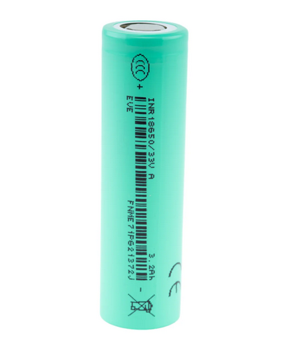
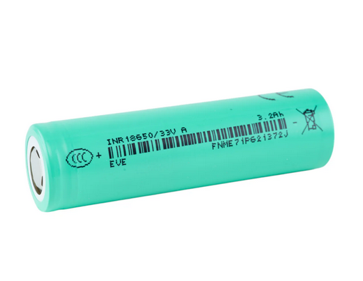
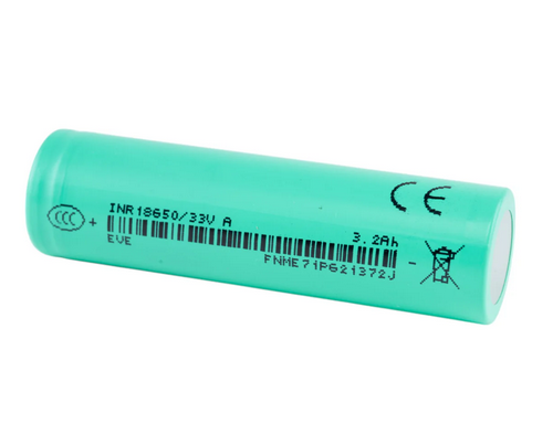


KEY SPECS · EVE ENERGY INR18650/33V
SOURCE [1]- SIZE
- Ø18.35 × 65.00 mm
- nominal ±0.10 / ±0.15 · with tube
- CAPACITY
- 3,200 mAh typ.
- 3,100 mAh min.
- 620 mA to 2.50 V
- CURRENT
- 10 A
- max. continuous
- 2.50 V cut-off
- TEMPERATURE
- −20 to 60 °C
- discharge · cell surface
- charge 0 to 50 °C · cell surface
EVE · 18650 · INR18650/33V
An 18650 lithium-ion cell, 3.60 V typical: 3,200 mAh typical and 3,100 mAh minimum, discharged at 620 mA to 2.50 V after a 1,550 mA standard charge [1] §3.1–§3.3, and a 10 A “Max. Continuous Discharge”, “DC, 10A, 2.50V cut-off”, with no temperature condition printed [1] §3.7. Below: every figure with its condition and its section in the specification, the percentages EVE’s tables print, and our arithmetic with its formula. EVE marks the specification confidential, so we quote it here and don’t link it; call or text us to check a figure against it.
CAPACITY, TYPICAL3,200 mAh3,100 mAh minimum; 620 mA to 2.50 V [1] §3.1, §3.2
MAX. CONTINUOUS10 A“DC, 10A, 2.50V cut-off”; no temperature condition printed [1] §3.7
STANDARD CHARGE1,550 mA0.5C, CC-CV to 4.20 ± 0.05 V, 62 mA cut-off [1] §3.4
ENERGY, CALCULATED11.52 Wh3.60 V typical × 3.200 Ah typical [1]; no document prints Wh
AC IMPEDANCE≤ 30 mΩinitial, AC 1 kHz, at the shipping state of charge (SOC) [1] §7.4
CELL WEIGHT46.0 g±2.0 g, as printed [1] §3.9
SDS [2]: Issue Date 2024-07-22, Validity “2024-07-22 ~2024-12-31” (printed validity ended 2024-12-31); we hold no later SDS. UN38.3 report [3]: effective date 2024-06-24. EVE’s specification [1] is quoted here, not linked: EVE marks every page confidential.
A bare cell: a component for protected packs and devices built for it. Not for vaping. Charge on a lithium-ion (Li-ion) charger that stops at 4.20 V.
01SPEC PLATE
Every figure, with its condition.
EVE’s data sheet for the 33V is a 16-page product specification [1]; this page calls it the specification. EVE marks every page confidential, so we quote it and don’t link it. It is the only version we hold: Version No. A, June, 2021. Its figures come first, copied as printed. Then the percentages its tables print, our arithmetic, and facts from the safety data sheet (SDS) [2] and the UN38.3 transport test report [3], both issued by testing labs. Each row names its source or shows its formula.
| SPECIFICATION | VALUE | CONDITION · SOURCE |
|---|---|---|
| AS PRINTED · MANUFACTURER copied from the specification [1] | ||
| MODEL | INR18650/33V | page header [1]; model name “EVE-INR18650/33V” [1] §2.2; the SDS, the UN38.3 report and the sleeve print “INR18650/33V A” [2][3] (fig 1.5) |
| CAPACITY, TYPICAL | 3,200 mAh | “Typical Discharge Capacity”; “Charge: 1550mA, 4.20V, CCCV 62mA cut-off” / “Discharge: 620mA, 2.50V DC cut-off” [1] §3.1 |
| CAPACITY, MINIMUM | 3,100 mAh | “Minimum Discharge Capacity”, the same charge and discharge [1] §3.2; “Minimum Discharge Capacity ≥ 3100mAh” at 25 °C after the standard charge, §7.3 |
| TYPICAL VOLTAGE | 3.60 V | “Typical Voltage”, as printed, in the table headed “Nominal Specifications”; no row is named nominal voltage [1] §3.3 |
| CHARGE VOLTAGE | 4.20 ± 0.05 V | “4.20±0.05V”, CC-CV (constant current, then constant voltage), in “3.4 Standard Charge” and “3.5 Rapid Charge” [1] §3.4, §3.5 |
| DISCHARGE CUT-OFF | 2.50 V | “2.50V cut-off” in “3.6 Standard Discharge” and “3.7 Max. Continuous Discharge”; range “4.20~2.50V”, the “Charge/Discharge Voltage Range” [1] §3.6–§3.8 |
| 1C | 3,100 mA | “1C (3100mA)” [1] §7.7; every C-rate in [1] is on this basis |
| STANDARD CHARGE | 1,550 mA | “CCCV, 0.5C (1550mA), 4.20±0.05V, 62mA cut-off” [1] §3.4; at 25 °C, §7.1 |
| RAPID CHARGE | 3,100 mA | “CCCV, 3100mA, 4.20±0.05V, 62mA cut-off (not for cycle life)” [1] §3.5; at 25 °C, §7.2 |
| CHARGE, 15 TO 50 °C | ≤ 3,100 mA | “≤ 1.0C (3100mA)” at “Charge: 15 to 50 °C”, “(Cell Surface Temperature)” [1] §3.11 |
| CHARGE, 0 TO 15 °C | ≤ 620 mA | “≤ 0.2C (620mA)” at “Charge: 0 to 15 °C”, cell surface [1] §3.11; no charge range below 0 °C or above 50 °C |
| STANDARD DISCHARGE | 620 mA | “DC, 620mA, 2.50V cut-off” [1] §3.6 |
| MAX. CONTINUOUS DISCHARGE | 10 A | “DC, 10A, 2.50V cut-off”; no temperature condition printed [1] §3.7 |
| DISCHARGE TEMPERATURE | −20 to 60 °C | “Discharge: -20 to 60°C”, cell surface [1] §3.11 |
| STORAGE TEMPERATURE | 0–25 °C | “0~25°C” for 1 year, “0~45°C” for 3 months, “0~60°C” for 1 month, “(At Shipping SOC)” [1] §3.12 |
| AC IMPEDANCE | ≤ 30 mΩ | “Initial Internal Impedance ≤ 30mΩ”, “at AC 1kHz at shipping SOC” [1] §7.4 |
| CYCLE LIFE | ≥ 70 % Ci | after 800 cycles of “Charge: 0.5C (1550mA), 4.20V, 155mA cut-off.” “Discharge: 1C (3100mA), 3.00V cut-off.” “Rest time: 10min after charge and 30min after discharge.”; Ci: “the first discharge capacity of cycle life test at 25±2°C” [1] §7.7 (fig 6.1) |
| SHIPPING VOLTAGE | 3.45–3.60 V | “20~30% SOC” [1] §7.9, §13.2 |
| CELL WEIGHT | 46.0 ± 2.0 g | “46.0±2.0g”, as printed [1] §3.9 |
| HEIGHT | 65.00 ± 0.15 mm | “Height: 65.00±0.15mm” [1] §3.10, “with tube” Fig. 1 |
| DIAMETER | 18.35 ± 0.10 mm | “Diameter: 18.35±0.10mm” [1] §3.10, “with tube” Fig. 1 |
| TEST CONDITIONS | 25 ± 2 °C | humidity “under 65% RH”, for every test in [1] “Unless otherwise specified” §6.1 |
| + Source: [1] EVE Energy Co., Ltd., PRODUCT SPECIFICATION, Lithium-ion rechargeable cell, Model: EVE-INR18650/33V, Spec. No. RD-EVE INR18650/33V-S143-LF, Version No. A, June, 2021 (as printed; 16 pages); on file; not linked, as EVE marks every page “-EVE Energy CO., LTD Confidential Proprietary-”. Call or text us with questions about its figures. | ||
| SPECIFICATION | VALUE | CONDITION · SOURCE |
|---|---|---|
| PRINTED IN THE SPECIFICATION’S TABLES percentages against their own printed basis (no mAh conversion) and the §13.2 sorting limits [1] | ||
| CAPACITY AT 3,100 mA (1.0C) | ≥ 90 % | “Relative capacity is divided by the discharge capacity of 620mA.” “2.50V cut-off after the standard charge” [1] §7.5 |
| CAPACITY AT 9,300 mA (3.0C) | ≥ 90 % | the same basis; the highest current in the table [1] §7.5 |
| DISCHARGE AT −20 °C | ≥ 70 % | 620 mA (0.2C) after the standard charge at 25 °C and 4 h of storage in a −20 °C test environment; “Relative capacity is divided by the 620mA discharge capacity at 25°C.” [1] §7.6 |
| DISCHARGE AT 55 °C | ≥ 90 % | the same basis [1] §7.6 |
| RETENTION, 28 DAYS AT 25 °C | ≥ 85 % | recovery ≥ 90 %; stored “fully standard charged”, against the “Initial Capacity: Standard discharge capacity.” [1] §7.8 |
| RETENTION, 7 DAYS AT 60 °C | ≥ 80 % | recovery ≥ 85 % [1] §7.8 |
| RECOVERY, 28 DAYS AT 45 °C | ≥ 85 % | retention printed “/” [1] §7.8 |
| VARIATION OF CAPACITY | ≤ 40 mAh | voltage “≤10mV”, AC impedance “≤3mΩ”; the group of cells is not stated [1] §13.2 |
| CALCULATED arithmetic on [1], shown so you can check it | ||
| ENERGY, CALCULATED | 11.52 Wh | 3.60 V typical × 3.200 Ah typical [1] §3.3, §3.1; no document prints a Wh figure |
| MAX. CONTINUOUS AS C-RATE | 3.23C | 10 A ÷ 3.1 A, the 1C of [1] §7.7; [1] prints no C-rate for 10 A |
| RUNTIME AT 620 mA | ≥ 5 h 00 min | 3,100 mAh minimum ÷ 620 mA [1] §3.2; about 5 h 10 min at the 3,200 mAh typical |
| CHARGE CUT-OFF AS C-RATE | 0.02C | 62 mA ÷ 3,100 mA [1] §3.4; the cycle-life test ends its charge at 155 mA, 0.05C [1] §7.7 |
| SIZE AND WEIGHT LIMITS | 64.85–65.15 mm | height, from 65.00 ± 0.15 mm; diameter 18.25–18.45 mm; weight 44.0–48.0 g [1] §3.9, §3.10 |
| VOLUME | 17.19 cm³ | π ÷ 4 × 18.35² × 65.00 mm³ at the printed size [1] §3.10; 16.96–17.42 cm³ across the tolerances |
| FROM THE SAFETY DATA SHEET (SDS) AND UN38.3 TEST REPORT copied as printed from [2] and [3] | ||
| MODEL | INR18650/33V A | Type/Model [2]; Name of Sample [3]; no document says what its trailing “A” means |
| FIGURES · SDS, UN38.3 | 3.6 V · 3,200 mAh | “3.6V, 3200mAh” under “Parameter” [2] Section 1; “3.6V 3200mAh” in the Name of Sample [3]; neither says typical, nominal or minimum or prints a condition |
| CATHODE | “LiNix |
“Cobalt lithium manganese nickel oxide”, “≤45.3%” in the column headed “Weigh 含量” (content) [2] Section 3; [1] names no cathode |
| TRANSPORT | UN 3480 | “UN 3480, LITHIUM ION BATTERIES”, “Class 9”, “PACKING INSTRUCTION 965, section IB” by air (IATA-DGR 65th Edition, 2024); UN 3481 (packed with or contained in equipment) “Not restricted”, “PACKING INSTRUCTION 966-967, section II”; by sea (IMDG Code, Amend 41-2022) and road (ADR-2023) “Not restricted, according to sp188”, in a “Strong package, Packaging in accordance to corresponding requirements of sp188” [2] Section 14 |
| UN38.3 REPORT | NO. |
T.1–T.6 and T.8 “Passed”; Shanghai Institute of Chemical Industry Testing Co., Ltd.; effective date 2024-06-24 [3] (section 07) |
| SAFETY DATA SHEET | YW20240715 |
Issue Date 2024-07-22, Validity “2024-07-22 ~2024-12-31” (printed validity ended 2024-12-31) [2] |
| STORAGE HUMIDITY · SDS | 45–85 % | “humidity: 45~85%” [2] Section 7; [1] prints no storage humidity |
| + Source: [1] EVE Energy Co., Ltd., PRODUCT SPECIFICATION, Lithium-ion rechargeable cell, Model: EVE-INR18650/33V, Spec. No. RD-EVE INR18650/33V-S143-LF, Version No. A, June, 2021 (as printed; 16 pages); on file; not linked, as EVE marks every page “-EVE Energy CO., LTD Confidential Proprietary-”. Call or text us with questions about its figures. + Source: [2] Guangzhou MCM Certification & Testing Co., Ltd., MATERIAL SAFETY DATA SHEET, Report No. YW20240715MSDS01 (as printed; no version printed), Type/Model “INR18650/33V A”, company “EVE Energy Co.,Ltd.”; Issue Date 2024-07-22, Validity “2024-07-22 ~2024-12-31” (printed validity ended 2024-12-31) · SDS PDF + Source: [3] Shanghai Institute of Chemical Industry Testing Co., Ltd., Test Report NO.1124050384 (as printed; no version printed), “Lithium-ion rechargeable cell INR18650/33V A 3.6V 3200mAh”, UN Manual of Tests and Criteria ST/SG/AC.10/11/Rev.8 Section 38.3; Test Date 2024-05-23 ~ 2024-06-24, effective date 2024-06-24; consignor “EVE Energy Co., Ltd.”, manufacturer “EVE Innovation Energy Co.,Ltd.” · UN38.3 report PDF | ||
PRINTED IN [1]FIG 1.1
Voltage window
2.50 V3.60 V4.20 Vcut-offtypicalcharge
Black marks: voltages printed in [1]: the “2.50V cut-off” of the standard and max. continuous discharge (§3.6, §3.7), the Typical Voltage “3.60V” (§3.3) and the charge voltage “4.20±0.05V” (§3.4). Orange band: the shipping range, “The cell should be shipped in 3.45V to 3.60V charging voltage range (20~30% SOC).” [1] §7.9.
PRINTED IN [1]FIG 1.2
Currents, as printed
Standard discharge “DC, 620mA, 2.50V cut-off” [1] §3.6
0.62 A
Max. continuous discharge “DC, 10A, 2.50V cut-off”; no temperature condition printed [1] §3.7
10 A
Standard charge “CCCV, 0.5C (1550mA), 4.20±0.05V, 62mA cut-off” [1] §3.4
1.55 A
Rapid charge “CCCV, 3100mA, 4.20±0.05V, 62mA cut-off (not for cycle life)” [1] §3.5
3.1 A
Charge limit, 15 to 50 °C “≤ 1.0C (3100mA)”, cell surface [1] §3.11
3.1 A
Charge limit, 0 to 15 °C “≤ 0.2C (620mA)”, cell surface [1] §3.11
0.62 A
Currents as printed in [1], each with its condition, drawn in amps. [1] prints the charge currents and the standard discharge in mA, with C-rates on its 1C of 3,100 mA; 10 A is 3.23C by our arithmetic (fig 3.2). Orange: the 10 A max. continuous discharge. [1] prints no pulse or other non-continuous rating.
PRINTED IN [1]FIG 1.3
Temperature ranges, as printed
Discharge “Discharge: -20 to 60°C”, cell surface [1] §3.11
Charge, at most 1.0C “Charge: 15 to 50 °C”, “≤ 1.0C (3100mA)” [1] §3.11
Charge, at most 0.2C “Charge: 0 to 15 °C”, “≤ 0.2C (620mA)” [1] §3.11
Storage, 1 year “0~25°C” at shipping SOC [1] §3.12
Table 7.6 test points −20, 25 and 55 °C, test environment [1] §7.6
Charge and discharge rows: cell surface, “(Cell Surface Temperature)” [1] §3.11. Orange: charging, in two bands with different current limits that share 15 °C as printed. Storage row: the §3.12 storage temperature at shipping SOC; fig 6.3 has all three. Last row: table 7.6’s test-environment temperatures (“after storage at the test environment”), not cell-surface readings; section 04 below. [1] prints no ambient charge or discharge range.
DOCUMENTS · [1]–[3]FIG 1.4
Capacity, as each document prints it
Typical, [1] §3.1 “3200mAh”, “Discharge: 620mA, 2.50V DC cut-off”
3,200
Minimum, [1] §3.2 “3100mAh”, the same charge and discharge; at 25 °C in §7.3
3,100
SDS [2] “3.6V, 3200mAh” under “Parameter”; no typical, nominal or minimum, no condition
3,200
UN38.3 report [3] “3.6V 3200mAh” in the Name of Sample; no typical, nominal or minimum, no condition
3,200
Sleeve, in the photo in [3] “3.2Ah”
3,200
Each document’s capacity figure, as printed, on a 3,000–3,300 mAh scale; the axis doesn’t start at zero. [1] labels 3,200 mAh Typical and 3,100 mAh Minimum, both “Discharge: 620mA, 2.50V DC cut-off” after “Charge: 1550mA, 4.20V, CCCV 62mA cut-off”; [2], [3] and the sleeve print “3200mAh” or “3.2Ah” without saying typical, nominal or minimum. No document prints a Wh figure: 11.52 Wh on this page is our arithmetic, 3.60 V × 3.200 Ah.
DOCUMENTS · [1]–[3]FIG 1.5
Model name, as each document prints it
| WHERE | AS PRINTED |
|---|---|
| [1] page header; Fig. 1 | “INR18650/33V” |
| [1] cover; §2.2 Model name | “EVE-INR18650/33V” |
| [2] Type/Model | “INR18650/33V A” |
| [3] Name of Sample | “INR18650/33V A” |
| Sleeve, in the photo in [3] | “INR18650/33V A” |
No document says what the trailing “A” means, so this page quotes each form as printed and doesn’t interpret it. The product title is our store’s name for the cell.
PRINTED IN [1]FIG 1.6
Sorting limits, as printed
| ITEM | SPEC. | REMARK |
|---|---|---|
| Minimum Capacity | 3100mAh | Charge: 1550mA, 4.20V, CCCV 62mA cut-off · Discharge: 620mA, 2.50V DC cut-off |
| Shipping Voltage | 3.45V to 3.60V | 20~30% SOC |
| Variation of Capacity | ≤40mAh | / |
| Variation of Voltage | ≤10mV | / |
| Variation of AC Impedance | ≤3mΩ | / |
Table 13.2 of [1], Sorting, copied as printed. It doesn’t say over which group of cells the variations apply, and it defines no grades. A guide when you match cells for a pack.
02 · CAPACITY
At 9,300 mA, ≥ 90 % of the 620 mA capacity.
Table 7.5 of EVE’s specification prints the 33V’s capacity at three currents, from 620 to 9,300 mA, each to 2.50 V after the standard charge, as a percent of the same cell’s capacity at 620 mA. At 9,300 mA (3.0C), the highest current in the table and just under the 10 A “Max. Continuous Discharge”, “DC, 10A, 2.50V cut-off” [1] §3.7, it prints ≥ 90 %: a minimum, not a reading. It prints no capacity in mAh at these currents.
620 mA · 0.2C100 %the basis: “Relative capacity is divided by the discharge capacity of 620mA.” [1] §7.5
9,300 mA · 3.0C≥ 90 %printed in [1] §7.5; 10 A ÷ 3.1 A = 3.23C, calculated
PRINTED IN [1]FIG 2.1
% of the capacity at 620 mA
808590951000246810100 % · 0.2C≥ 90 % · 1.0C≥ 90 % · 3.0C10 A max.
continuous,
to 2.50 V
Discharge current, A
continuous,
to 2.50 V
Data: table 7.5 of [1], Discharge Rate Capabilities · “2.50V cut-off after the standard charge” · percent of the same cell’s 620 mA capacity · ≥ figures are minimums · the points stand alone: EVE prints no curve between them · vertical line: the 10 A “Max. Continuous Discharge”, “DC, 10A, 2.50V cut-off” [1] §3.7 · no temperature in §7.5; §6.1 sets “25±2°C” “Unless otherwise specified” · axis starts at 80 % · data table under fig 3.1
03BY CURRENT
Capacity, by current.
Table 7.5 of [1] prints the capacity at 620, 3,100 and 9,300 mA as a percent of the same cell’s capacity at 620 mA. It prints no mAh at those currents, so this page doesn’t convert them. The C-rates use the 1C of [1], 3,100 mA.
PRINTED IN [1]FIG 3.1
Relative capacity, by current
Table 7.5 of [1]: capacity at each current, “2.50V cut-off after the standard charge”, as a percent: “Relative capacity is divided by the discharge capacity of 620mA.” ≥ figures are minimums. [1] prints no mAh and no temperature here (§6.1’s “25±2°C” applies “Unless otherwise specified”). Orange: 9,300 mA (3.0C), the table’s highest current.
DATA TABLE · FIG 3.1
| CURRENT | RATE | RELATIVE CAPACITY |
|---|---|---|
| 620mA | 0.2C | 100% |
| 3100mA | 1.0C | ≥90% |
| 9300mA | 3.0C | ≥90% |
PRINTED IN [1] + CALCULATEDFIG 3.2
Currents on the 1C basis
Standard discharge 620 mA, “0.2C” in §7.5 and §7.6 [1]
0.2C
Standard charge “0.5C (1550mA)” [1] §3.4
0.5C
Rapid charge “3100mA (1C)” [1] §7.2; “(not for cycle life)” §3.5
1C
Cycle-life discharge “1C (3100mA)” to “3.00V cut-off” [1] §7.7
1C
Table 7.5 currents 620, 3,100 and 9,300 mA: “0.2C”, “1.0C”, “3.0C” [1] §7.5
Max. continuous discharge 10 A ÷ 3.1 A = 3.23C, our arithmetic; “DC, 10A, 2.50V cut-off” [1] §3.7
3.23C
Every C-rate [1] prints is on one basis, “1C (3100mA)” (§7.7), numerically the 3,100 mAh minimum capacity; [1] doesn’t say which capacity defines C. Of the currents charted, only 10 A has no printed C-rate: 10 A ÷ 3.1 A = 3.23C, our arithmetic. The 62 mA and 155 mA charge cut-offs have none either (0.02C and 0.05C by our arithmetic, spec plate). Orange: the 10 A max. continuous discharge.
What 10 A means
- 10 A is the “Max. Continuous Discharge”: “DC, 10A, 2.50V cut-off” [1] §3.7. Some makers rate continuous current only with a cell-temperature cut-off (the 80 °C cut-offs in section 08). EVE prints no temperature condition with 10 A and no temperature rise at it, and we have no reading of our own. Separately, §3.11 sets the cell’s discharge range for any current: discharge only while the cell surface is between −20 and 60 °C (“Discharge: -20 to 60°C”). §12.3.2: “The cell shall be discharged within a range of temperatures specified in the specification.”
- On the 1C of [1], 3,100 mA, 10 A is 3.23C (fig 3.2). Table 7.5 stops at 9,300 mA (3.0C), ≥ 90 % of the 620 mA capacity; [1] prints no capacity at 10 A.
- [1] §12.3.1: “The cell shall be discharged continuously at less than maximum discharging current specified in the specification.”
- [1] prints no pulse, peak or other non-continuous discharge rating, so this page shows none.
04TEMPERATURE
Capacity in the cold and the heat.
Table 7.6 of [1] prints the capacity at −20, 25 and 55 °C, discharged at 620 mA (0.2C) after a standard charge at 25 °C and 4 h at the test temperature, as a percent of the 25 °C figure. At −20 °C, the coldest test environment in the table, it prints ≥ 70 %; §3.11 allows discharge down to −20 °C at the cell surface.
PRINTED IN [1]FIG 4.1
Relative capacity, by discharge temperature
Capacity when the discharge runs at each temperature, “with discharge constant current 620mA (0.2C) and 2.50V cut-off after the standard charge at 25°C”, after 4 h at the test temperature (the printed Storage Time). Printed in table 7.6 of [1] as a percent: “Relative capacity is divided by the 620mA discharge capacity at 25°C.” Each ≥ figure is a minimum. Orange: −20 °C, the coldest test temperature in table 7.6.
DATA TABLE · FIG 4.1
| TEMPERATURE | STORAGE TIME | RELATIVE CAPACITY |
|---|---|---|
| -20°C | 4h | ≥70% |
| 25°C | 4h | 100% |
| 55°C | 4h | ≥90% |
PRINTED IN [1]FIG 4.2
Discharge temperature, range and table
Discharge “Discharge: -20 to 60°C”, cell surface [1] §3.11
Table 7.6 points −20, 25 and 55 °C test environment: ≥ 70 %, 100 %, ≥ 90 % [1] §7.6
Charge 0 to 50 °C in two bands, cell surface [1] §3.11 (fig 5.1)
Test condition “25±2°C”, “Unless otherwise specified” [1] §6.1
The discharge range and charge bands are cell-surface temperatures, as [1] §3.11 prints them. The table 7.6 points are test-environment temperatures (4 h at each), and gray marks §6.1’s test condition, “25±2°C”: neither is a cell-surface reading. The cell may discharge from −20 °C but not charge below 0 °C at the cell surface (orange). [1] prints no ambient charge or discharge range.
05CHARGING
Charging: 1,550 mA standard, 3,100 mA rapid.
The specification prints two charges, both CC-CV (constant current, then constant voltage) to “4.20±0.05V” with a 62 mA cut-off: a 1,550 mA standard charge and a 3,100 mA rapid charge, “(not for cycle life)” [1] §3.4, §3.5. It limits the charge current by cell surface temperature (§3.11) and prints no charge time.
PRINTED IN [1]FIG 5.1
Charge-current limit, by cell surface temperature
mA
01,0002,0003,000−20015255060≤ 0.2C≤ 1.0CStandardRapidnone
printed
Cell surface temperature, °C
printed
The charge-current limit [1] §3.11 prints for each band of cell surface temperature: “≤ 0.2C (620mA)” at “Charge: 0 to 15 °C” and “≤ 1.0C (3100mA)” at “Charge: 15 to 50 °C”; the bands share 15 °C as printed. [1] prints no charge range outside 0 to 50 °C. Points: the Standard Charge, 1,550 mA (0.5C), and the Rapid Charge, 3,100 mA (1C), both defined “at 25°C” [1] §7.1, §7.2, a test temperature, not a cell-surface reading; drawn at 25 °C for reference. From 0 to 15 °C the standard charge is above the limit, so charge at 620 mA or less there.
DATA TABLE · FIG 5.1
| TEMPERATURE | CHARGE CURRENT, AS PRINTED |
|---|---|
| Charge: 0 to 15 °C, cell surface | ≤ 0.2C (620mA) |
| Charge: 15 to 50 °C, cell surface | ≤ 1.0C (3100mA) |
| Standard Charge, at 25 °C, a test temperature | CCCV, 0.5C (1550mA), 4.20±0.05V, 62mA cut-off |
| Rapid Charge, at 25 °C, a test temperature | CCCV, 3100mA, 4.20±0.05V, 62mA cut-off (not for cycle life) |
PRINTED IN [1]FIG 5.2
Voltage thresholds, as printed
Working range “4.20~2.50V” [1] §3.8
Charge voltage “4.20±0.05V”, CC-CV [1] §3.4, §3.5
Discharge cut-off “2.50V cut-off” [1] §3.6, §3.7
Shipping voltage “3.45V to 3.60V”, “20~30% SOC” [1] §7.9, §13.2
Long-term storage “from 3.50V to 3.80V”, 3 months or more [1] §13.1
Cycle-life test cut-off “3.00V cut-off” [1] §7.7
Voltages as printed in [1]. Orange: the working range. A pack’s battery management system (BMS) should keep each cell inside it: [1] §12.3.3 asks for “a device to prevent further discharging exceeding discharging cut-off voltage”. The scale starts at 2.0 V.
Before you charge
- Use a lithium-ion charger with a CC-CV profile that stops at 4.20 V: [1] prints “4.20±0.05V” (§3.4).
- Standard charge: “CCCV, 0.5C (1550mA), 4.20±0.05V, 62mA cut-off” [1] §3.4. Rapid charge: 3,100 mA, “(not for cycle life)” §3.5; the cycle-life criterion (§7.7) uses the 1,550 mA charge. [1] prints no charge time and no higher charge current.
- At the cell surface: “≤ 1.0C (3100mA)” at “Charge: 15 to 50 °C”, and “≤ 0.2C (620mA)” at “Charge: 0 to 15 °C” [1] §3.11. Below 0 °C or above 50 °C, don’t charge.
- Never charge in reverse: “Inverse charging shall be strictly prohibited.” [1] §12.2.4.
- In a pack, a battery management system (BMS) should end charge at 4.20 V per cell and stop on temperature; [1] §12.6.6 asks for a device to “monitor each voltage of cell block”.
EVE draws no chart of the charge bands: fig 5.1 plots the table of [1] §3.11, and fig 5.2 sets the voltages [1] prints on one scale.
06CYCLE LIFE AND STORAGE
What it keeps after use and storage.
[1] §7.7 sets at least 70 % of Ci, the capacity of the test’s own first discharge, after 800 cycles of a 0.5C (1,550 mA) charge to 4.20 V with a 155 mA cut-off and a 1C (3,100 mA) discharge to 3.00 V, and §7.8 prints the retention and recovery ratios after “fully standard charged storage” at 25 and 60 °C, and the recovery ratio only at 45 °C. It prints no cycle-life curve, so the charts show only its printed points.
PRINTED IN [1]FIG 6.1
Cycle life, as printed
The cycle-life clause of [1] §7.7, as printed: “Charge: 0.5C (1550mA), 4.20V, 155mA cut-off.” “Discharge: 1C (3100mA), 3.00V cut-off.” “Rest time: 10min after charge and 30min after discharge.” “Capacity after 800 cycles.” “Capacity ≥ 70% Ci (Ci: the first discharge capacity of cycle life test at 25±2°C)”. 70 % is of Ci, the test’s own first discharge, not of the 3,200 mAh typical or 3,100 mAh minimum, and each discharge stops at 3.00 V, not 2.50 V. Orange: after 800 cycles. A criterion, not a curve: [1] prints no capacity between the first cycle and cycle 800.
PRINTED IN [1]FIG 6.2
Retention and recovery after storage
Retention: the first discharge after storageRecovery, in gray figures: after three cycles
Capacity after storage “fully standard charged” at each temperature and time, as a percent of the “Initial Capacity: Standard discharge capacity.” [1] §7.8: “Retention Ratio= Retention Capacity/ Initial Capacity*100%”, “Recovery Ratio= Recovery Capacity/ Initial Capacity*100%”. Recovery is “The standard discharge capacity of three times cycles after fully standard charged storage”. Each ≥ figure is a minimum; for 28 days at 45 °C, [1] prints “/” for retention, so no bar. [1] §12.4.2: “storage with higher voltage may cause more loss of performance characteristics.”
PRINTED IN [1]FIG 6.3
Storage temperature, by time
1 month “0~60°C” [1] §3.12
3 months “0~45°C” [1] §3.12
1 year “0~25°C” [1] §3.12
3 months or more “normally 0~25°C”, at “3.50V to 3.80V” [1] §13.1
Table 7.8 storage tests 25, 45 and 60 °C, fully charged [1] §7.8 (fig 6.2)
Storage temperature by time, as printed in [1] §3.12, “(At Shipping SOC)”: “20~30% SOC”, 3.45 to 3.60 V (§7.9). For 3 months or more, §13.1 says “it is strongly recommended that the cell is performed one cycle”, with the environment “dry and no corrosive gas”. The SDS adds a storage humidity: “humidity: 45~85%” [2] Section 7. Orange: the 1-year range, the narrowest. Last row: the temperatures of table 7.8, whose cells were stored fully charged.
07TRANSPORT TESTS
What the UN38.3 report records.
UN38.3 is the set of transport tests for lithium cells and batteries in the UN Manual of Tests and Criteria, Section 38.3. The test report [3] from Shanghai Institute of Chemical Industry Testing Co., Ltd., effective 2024-06-24, records “Passed” for T.1 to T.6 and T.8 on the “INR18650/33V A”, with each sample’s result, at “Ambient temperature:20℃-24℃” as printed. It names the consignor “EVE Energy Co., Ltd.” and the manufacturer “EVE Innovation Energy Co.,Ltd.” as printed, and under Appearance describes its samples as “Green Cylinder plastics film shell”. The lab’s samples, not our lot.
PRINTED IN [3]FIG 7.1
Highest surface temperature, T.5 and T.6
T.5 External short circuit 5 samples, “1CYC Fully charged” · 108.7–122.0 °C
T.5 External short circuit 5 samples, “25CYC Fully charged” · 114.4–123.0 °C
T.6 Impact 5 samples, “1CYC 50% Capacity” · 22.9–25.8 °C
T.6 Impact 5 samples, “25CYC 50% Capacity” · 22.9–25.7 °C
Each sample’s “Max. External Temperature /℃” in [3]: one tick per sample, and equal readings share a tick; the orange bar spans the lowest to the highest. T.5: samples 001–010, fully charged, the same samples that ran T.1 to T.4. T.6: samples 011–020, at 50 % capacity. “1CYC” and “25CYC” are the sample states as printed. The lab’s ambient, as printed: “Ambient temperature:20℃-24℃” [3]. [3] prints no short-circuit resistance, impact parameters or temperature limit. It records “Passed” for both tests and “O” for each sample: “O-No Disassembly,No Fire & No Rupture.” (T.5), “O-No Disassembly & No Fire.” (T.6). Sample counts are our tally of the printed rows. The lab’s samples, not our lot.
DATA TABLE · FIG 7.1
| TEST | SAMPLES | MAX. °C, EACH SAMPLE |
|---|---|---|
| T.5 External short circuit | 001–010 | 108.7, 122.0, 113.0, 120.7, 113.0, 114.4, 117.3, 117.3, 116.3, 123.0 |
| T.6 Impact | 011–020 | 25.8, 22.9, 24.5, 25.8, 25.5, 25.2, 25.7, 25.5, 24.4, 22.9 |
PRINTED IN [3]FIG 7.2
Voltage kept through T.1–T.4
T.1 Altitude simulation 99.76–100.00 % [3] · 10 samples
T.2 Thermal test 98.09–98.80 % [3] · 10 samples
T.3 Vibration 100.00 % [3] · 10 samples
T.4 Shock 99.76–100.00 % [3] · 10 samples
Open-circuit voltage after each test as a percent of the voltage before it, printed for each of the 10 samples in [3] as “Residual OCV /%”: one tick per distinct value; samples with equal values share a tick. The same samples ran T.1 to T.4 in turn, starting fully charged at 4.17–4.19 V. Mass loss was 0.01 % or less for each sample in each test. [3] prints no numeric pass criterion; it records “Passed” for each test and “O” for each sample: “O-No Leakage,No Venting, No Disassembly,No Rupture & No Fire.” Sample counts are our tally of the printed rows. The scale starts at 97 %.
DATA TABLE · FIG 7.2
| SAMPLE | T.1 % | T.2 % | T.3 % | T.4 % |
|---|---|---|---|---|
| 001 | 100.00 | 98.09 | 100.00 | 100.00 |
| 002 | 99.76 | 98.33 | 100.00 | 99.76 |
| 003 | 100.00 | 98.56 | 100.00 | 99.76 |
| 004 | 99.76 | 98.80 | 100.00 | 100.00 |
| 005 | 100.00 | 98.56 | 100.00 | 100.00 |
| 006 | 99.76 | 98.33 | 100.00 | 99.76 |
| 007 | 99.76 | 98.80 | 100.00 | 100.00 |
| 008 | 100.00 | 98.09 | 100.00 | 99.76 |
| 009 | 100.00 | 98.56 | 100.00 | 100.00 |
| 010 | 100.00 | 98.56 | 100.00 | 100.00 |
PRINTED [1][3] + CALCULATEDFIG 7.3
Mass of the samples the lab weighed
g
44.045.046.047.048.01234567891046.0±2.0g [1] §3.9
Sample, 001–010
Mass of the 10 samples the lab weighed before T.1, as printed in [3]: 44.0329–44.7507 g (mean 44.34 g, our arithmetic). All the masses [3] prints for them, before and after T.1 to T.4, lie between 44.0308 and 44.7512 g: inside the “46.0±2.0g” of [1] §3.9 (dotted lines at 46.0 g and at 44.0 and 48.0 g, the limits by our arithmetic), near its lower end. The axis starts at 43.5 g. The lab weighed 10 of the 40 samples it lists; they are its samples, not our lot.
DATA TABLE · FIG 7.3
| SAMPLE | BEFORE T.1 g | AFTER T.1 | AFTER T.2 | AFTER T.3 | AFTER T.4 |
|---|---|---|---|---|---|
| 001 | 44.1789 | 44.1771 | 44.1774 | 44.1780 | 44.1764 |
| 002 | 44.2138 | 44.2096 | 44.2124 | 44.2140 | 44.2133 |
| 003 | 44.1282 | 44.1266 | 44.1283 | 44.1270 | 44.1261 |
| 004 | 44.5626 | 44.5617 | 44.5631 | 44.5626 | 44.5609 |
| 005 | 44.3801 | 44.3773 | 44.3796 | 44.3805 | 44.3798 |
| 006 | 44.0995 | 44.0970 | 44.0987 | 44.1008 | 44.0995 |
| 007 | 44.5790 | 44.5774 | 44.5789 | 44.5793 | 44.5782 |
| 008 | 44.0329 | 44.0308 | 44.0314 | 44.0335 | 44.0328 |
| 009 | 44.7507 | 44.7480 | 44.7492 | 44.7512 | 44.7507 |
| 010 | 44.5239 | 44.5208 | 44.5229 | 44.5254 | 44.5248 |
What the report records
| TEST | SAMPLES | SAMPLE STATUS, AS PRINTED | RESULT |
|---|---|---|---|
| T.1 Altitude simulation | 001–010 | “1CYC Fully charged”, “25CYC Fully charged” | “Passed” |
| T.2 Thermal test | 001–010 | “1CYC Fully charged”, “25CYC Fully charged” | “Passed” |
| T.3 Vibration | 001–010 | “1CYC Fully charged”, “25CYC Fully charged” | “Passed” |
| T.4 Shock | 001–010 | “1CYC Fully charged”, “25CYC Fully charged” | “Passed” |
| T.5 External short circuit | 001–010 | “1CYC Fully charged”, “25CYC Fully charged” | “Passed” |
| T.6 Impact | 011–020 | “1CYC 50% Capacity”, “25CYC 50% Capacity” | “Passed” |
| T.8 Forced discharge | 021–040 | “1CYC Fully discharged”, “25CYC Fully discharged” | “Passed” |
Copied from the test item summary and appendices of [3]; sample numbers as printed, counts our tally (40 samples in all). [3] prints one test condition, its Test Environment Condition, “Ambient temperature:20℃-24℃” (humidity printed “/%”), each sample’s state and readings, and “Passed” for each test; it prints no test currents, durations, test temperatures or pass limits. The SDS cites the same report: “The battery has passed the test items of UN Manual of Test and Criteria Section 38.3, and Report No.: 1124050384.” [2]
EVE’s own test methods
| TEST | EVE’S TEST METHOD, CONDENSED FROM [1] | PASS CRITERION, AS PRINTED | SECTION |
|---|---|---|---|
| Free fall test | Fully standard charged cell dropped three times from 1.0m onto a flat concrete floor at 20±5°C, impacts in random orientations; then at least 1h rest and a visual inspection. | “No fire, no explosion.” | [1] §8.1 |
| Vibration test | Sinusoidal vibration, logarithmic sweep 7Hz to 200Hz and back in 15 minutes, 12 times (3 hours) in each of three perpendicular mounting positions: 1 gn peak to 18 Hz, then 0.8 mm amplitude (1.6 mm total excursion) to 8 gn, then 8 gn to 200 Hz. | “No fire, no explosion, no leakage, with less than 10% of OCV drop.” | [1] §8.2 |
| Overcharge test | Fully standard discharged cell charged at 3100mA to 6.3V, or for at most 1h. | “No fire, no explosion.” | [1] §9.1 |
| External Short-circuit test | Fully standard charged cell short-circuited through a load of less than 5mΩ for 10min. | “No fire, no explosion.” | [1] §9.2 |
| Forced Discharge test | Fully standard discharged cell force-discharged at 3100mA (1C) for 90 min. | “No fire, no explosion.” | [1] §9.3 |
| Heating test | Standard charged cell heated at 5°C±2°C per minute to 130°C±2°C, then kept in the oven for 30 minutes. | “No fire, no explosion.” | [1] §9.4 |
| Altitude Simulation test | Fully standard charged cell stored at 11.6 kPa or less for at least six hours at ambient temperature (20±5°C). | “No fire, no explosion and no leakage with less than 10% of OCV drop.” | [1] §9.5 |
| Thermal test | Fully standard charged cell held at least 90 minutes at -40±2°C, then at least 110 minutes at 85±2°C, with timed transitions; 5 cycles. | “No fire, no explosion.” | [1] §9.6 |
| Crush Test | Fully standard charged cell crushed between two flat surfaces, its axis parallel to them, until a force of 13±1 kN is reached. | “No fire, no explosion.” | [1] §9.7 |
EVE’s test method and pass criterion for each test in [1] §8 and §9: methods condensed, keeping their numbers and symbols; criteria quoted. [1] lists them as requirements for the cell and prints no results. Each method also names a test standard. Naming a standard in a test method isn’t a certificate, and no certificate to any of those standards is on file; the UN38.3 test report [3] is on file and linked. These are EVE’s requirements, not the tests in [3]: the UN38.3 report ran its own tests on its own samples (above).
08COMPARE
Where the 33V sits.
Thirteen other 18650 cells, each from its own manufacturer document. The documents don’t rate discharge the same way: some print a continuous figure, some a maximum, the 26V’s neither, and their conditions differ, so the table quotes each document’s wording.
DOCUMENTS · [1][4]FIG 8.1
Minimum capacity and discharge, side by side
- Molicel P28B INR-18650-P28B2,650 mAh minimum · 2,800 typical40 A continuous · 80 °C cut-off
- Molicel P28A INR-18650-P28A2,700 mAh minimum · 2,800 typical35 A maximum · 80 °C cut-off
- Molicel P26A INR-18650-P26A2,500 mAh minimum · 2,600 typical35 A maximum · no condition printed
- Sony/Murata VTC6 US18650VTC63,000 mAh minimum · 3,120 nominal30 A continuous · 80 °C cut-off; 15 A without a cut-off
- Samsung 30Q INR18650-30Q62,950 mAh minimum · 3,000 nominal30 A continuous · 80 °C cut-off; 15 A without a cut-off
- Molicel P30B INR-18650-P30B2,900 mAh minimum · 3,000 typical30 A continuous · 80 °C cut-off
- EVE 25P INR18650/25P2,450 mAh minimum · 2,500 nominal30 A continuous · 2.50 V cut-off in its specification; no temperature condition printed
- Samsung 25R INR18650-25R2,500 mAh minimum · typical not stated by manufacturer20 A continuous · at room temperature
- LG HG2 18650HG2Minimum not stated by manufacturer · 3,000 nominal20 A continuous · no temperature condition printed
- EVE 35V INR18650/35V3,400 mAh minimum · 3,500 typical10.2 A maximum, not for cycle life · 2.50 V cut-off; no temperature condition printed
- Molicel M35A INR-18650-M35A3,350 mAh minimum · 3,450 typical10 A maximum · no condition printed
- EVE 33V INR18650/33V3,100 mAh minimum · 3,200 typical10 A continuous · 2.50 V cut-off; no temperature condition printed
- Samsung 35E INR18650-35E3,350 mAh minimum · typical not stated by manufacturer8 A continuous · no temperature condition printed
- EVE 26V ICR18650/26V2,500 mAh minimum · 2,550 typicalnone printed EVE’s current 26V specification prints no continuous or maximum discharge rating
Bars show each printed figure, not like-for-like ratings. Beside each bar: the kind of figure its document prints, then its condition; the conditions differ, from an 80 °C cut-off to a 2.50 V cut-off or none printed. The P28A, P26A and M35A documents print a maximum discharging current, and the 35V document prints a maximum marked “(Not for cycle life)”; EVE’s current 26V specification prints no continuous or maximum discharge rating, so the 26V has no discharge bar; the others print continuous figures. Where a note says no temperature condition is printed, that doesn’t mean the figure holds without a temperature cut-off: only the VTC6 and 30Q documents print a separate, lower figure for that case, and their bars show the higher one. Orange: the 33V, from [1]; the others are copied from their own documents [4]. Bars start at zero: minimum capacity on a 0–3,500 mAh scale, discharge on 0–40 A. Pulse and instantaneous figures, which are not ratings for a steady load, and figures printed as not for continuous discharge (the 35E’s second discharge figure) are left out.
| CELL | TYPICAL OR NOMINAL mAh | MINIMUM mAh | DISCHARGE KIND | DISCHARGE AS PRINTED | CHARGE AS PRINTED | MASS g |
|---|---|---|---|---|---|---|
| Molicel P28B INR-18650-P28B |
2,800 typical | 2,650 | continuous | “Discharge Current” “Continuous” “40 A (80oC cut-off)” | “Charge Current” “Maximum” “8.4 A (70oC cut-off)” | 48 max |
|
Molicel P28A INR-18650-P28A |
2,800 typical | 2,700 | maximum | “Maximum discharging current” “35A (with 80 oC temp. cut)”; remark “Cycle life is reduced at high rates.” | “Maximum charging current” “8.4A”; remark “See Section 4.14” | 48 max |
|
Molicel P26A INR-18650-P26A |
2,600 typical | 2,500 | maximum | “Maximum discharging current” “35A”, no condition printed | “Maximum charging current” “6A”, no condition printed | 48 max |
|
Sony/Murata VTC6 US18650VTC6 |
3,120 nominal | 3,000 | continuous | “Continuous Maximum Discharge Current” “30A” “(With 80 deg temperature cut)” and “15A” “(Without 80 deg temperature cut)” | “Continuous Maximum Charge Current” “5.0A” “Continuous”; its pulse figure is left out, as a pulse figure is not a rating | 46.6 typical |
|
Samsung 30Q INR18650-30Q6 |
3,000 nominal | 2,950 | continuous | “Max. continuous discharge (Surface temperature)” “15A(Without temperature cut)” and “30A(With 80℃ temperature cut)” | “Rated charge” “CCCV, 4A, 4.20V, 100mA cut-off” | 48 max |
|
Molicel P30B INR-18650-P30B |
3,000 typical | 2,900 | continuous | “Discharge Current” “Continuous” “30 A (80oC cut-off)” | “Charge Current” “Maximum” “9 A (60oC cut-off)” | 47 max |
|
EVE 25P INR18650/25P |
2,500 nominal | 2,450 | continuous | “Max. continuous discharge current” “30.0A” (data sheet; no condition printed); “Max. Continuous Discharge” “DC, 30A, 2.50V cut-off” (specification §3.6) | “Max. continuous charge current” “4.0A” (data sheet; no condition printed); the same 4 A appears as “Rapid Charge” “CCCV, 4A, 4.20±0.05V, 100mA cut-off” (specification §3.4) | 48 max |
|
Samsung 25R INR18650-25R |
Not stated by manufacturer | 2,500 | continuous | “Max. continuous discharge” “20A (@ RT)” | “Rated charge” “CCCV, 4A, 4.20V, 100mA cut-off” | 45 max |
| LG HG2 18650HG2 |
3,000 nominal | Not stated by manufacturer | continuous | “Max. Discharge Current” “For continuous discharge” “20000mA” | “Max. Charge Current” “4000mA”, no condition printed | 48 max |
|
EVE 35V INR18650/35V |
3,500 typical | 3,400 | maximum, not for cycle life | “Max. Discharge” “DC, 10.2A, 2.50V cut-off (Not for cycle life)” (specification §3.7) | “Charge: 15 to 50 °C” “≤1.0C (Not for cycle life)”, the charge-current limit for that band of cell surface temperature (specification §3.11); 1C is printed as “3.4A(1C)” (specification §9.1), so 1.0C is 1.0 × 3.4 A = 3.4 A, our arithmetic | 50 max |
|
Molicel M35A INR-18650-M35A |
3,450 typical | 3,350 | maximum | “Maximum discharging current” “10 A”, no condition printed; remark “Cycle life is reduced at high rates.” | “Maximum charging current” “1.7 A”; remark “See Section 4.14” | 48 max |
| EVE 33V INR18650/33V |
3,200 typical | 3,100 | continuous | “Max. Continuous Discharge” “DC, 10A, 2.50V cut-off” ([1] §3.7) | “Charge: 15 to 50 °C” “≤ 1.0C (3100mA)”, the charge-current limit for that band of cell surface temperature ([1] §3.11) | 46.0±2.0 as printed |
|
Samsung 35E INR18650-35E |
Not stated by manufacturer | 3,350 | continuous | “Max. Discharge Current” “8,000mA (for continuous discharge)”; its second figure, printed as not for continuous discharge, is left out | “Max. Charge Current” “2,000mA (not for cycle life)” | 50 max |
|
EVE 26V ICR18650/26V |
2,550 typical | 2,500 | none printed | none printed: EVE’s current 26V specification prints no continuous or maximum discharge rating. Its only discharge figure labeled “Max.” is its “Max. Instantaneous Discharge” (specification §3.7), an instantaneous figure, so the chart leaves it out | “Charge: 15 to 45 °C” “≤1.25A”, the charge-current limit for that band of cell surface temperature (specification §3.11) | 48 max |
Text in quotation marks is copied as printed from each manufacturer document: the specification [1] for the 33V, and for the others the newest version we hold [4], checked by a second reading. Where a document prints a row label, a sub-label, a value and a remark in separate cells, each is quoted on its own. Molicel’s documents print a raised letter o in place of the degree sign; the quotations keep the letter. Everything outside quotation marks is ours, the discharge kind included: continuous where the document prints the word continuous, maximum where it prints only Max. or Maximum, and none printed for the 26V, whose only discharge figure labeled “Max.” is instantaneous. Linked names go to that cell’s listing in our store.
09PACK MATH
From one cell to a pack.
How the single-cell figures scale in series (S) and parallel (P). Illustrative arithmetic, not a pack rating.
V MAX4.2 × S
charge voltage, 4.20 ± 0.05 V [1] §3.4
V TYPICAL3.6 × S
Typical Voltage, 3.60 V [1] §3.3
CAPACITY3.1 × P
Ah minimum; 3.2 × P typical; 620 mA to 2.50 V [1] §3.1, §3.2
CONTINUOUS10 × P
A, max. continuous discharge, DC, 2.50 V cut-off [1] §3.7*
| CONFIG | CELLS | V MAX | V TYPICAL | Ah MINIMUM | Ah TYPICAL | Wh, CALCULATED | DISCHARGE A* | CHARGE A, 15–50 °C* | CELL MASS g |
|---|---|---|---|---|---|---|---|---|---|
| 1S1P | 1 | 4.2 | 3.6 | 3.10 | 3.20 | 11.5 | 10 | 3.1 | 46 |
| 2S1P | 2 | 8.4 | 7.2 | 3.10 | 3.20 | 23.0 | 10 | 3.1 | 92 |
| 3S1P | 3 | 12.6 | 10.8 | 3.10 | 3.20 | 34.6 | 10 | 3.1 | 138 |
| 4S1P | 4 | 16.8 | 14.4 | 3.10 | 3.20 | 46.1 | 10 | 3.1 | 184 |
| 2S2P | 4 | 8.4 | 7.2 | 6.20 | 6.40 | 46.1 | 20 | 6.2 | 184 |
| 3S2P | 6 | 12.6 | 10.8 | 6.20 | 6.40 | 69.1 | 20 | 6.2 | 276 |
| 4S2P | 8 | 16.8 | 14.4 | 6.20 | 6.40 | 92.2 | 20 | 6.2 | 368 |
| 7S3P | 21 | 29.4 | 25.2 | 9.30 | 9.60 | 241.9 | 30 | 9.3 | 966 |
| 10S3P | 30 | 42.0 | 36.0 | 9.30 | 9.60 | 345.6 | 30 | 9.3 | 1,380 |
| 10S4P | 40 | 42.0 | 36.0 | 12.40 | 12.80 | 460.8 | 40 | 12.4 | 1,840 |
| 13S4P | 52 | 54.6 | 46.8 | 12.40 | 12.80 | 599.0 | 40 | 12.4 | 2,392 |
| 14S5P | 70 | 58.8 | 50.4 | 15.50 | 16.00 | 806.4 | 50 | 15.5 | 3,220 |
CALCULATED FROM [1]FIG 9.1
Current ceilings, by parallel count
3.1 A × P, charge limit at 15 to 50 °C [1] §3.1110 A × P, max. continuous discharge [1] §3.7
The single-cell figures times the parallel count: ceilings before derating, not pack ratings. The charge limit holds at a cell surface temperature of 15 to 50 °C, and [1] §3.11 sets discharge at a cell surface of −20 to 60 °C; it prints no temperature rise at 10 A.
* Single-cell figures × cells in parallel: the 10 A “Max. Continuous Discharge”, “DC, 10A, 2.50V cut-off” [1] §3.7, with no temperature condition printed, and the charge limit at the cell surface, “≤ 1.0C (3100mA)” from 15 to 50 °C (“≤ 0.2C (620mA)” from 0 to 15 °C) §3.11. At 3,100 mA per cell this is EVE’s Rapid Charge, “(not for cycle life)” §3.5; its Standard Charge is 1,550 mA per cell (§3.4), the current its 800-cycle criterion uses (§7.7). Wh = 3.60 V × 3.200 Ah × S × P, our arithmetic on the Typical Voltage and Typical Discharge Capacity [1] §3.3, §3.1; no document prints a Wh figure. Cell mass = 46.0 g × S × P, cells only [1] §3.9. Derate so each cell’s surface stays within −20 to 60 °C while discharging (§3.11); size the BMS, fusing and interconnects for the derated current; use matched cells of one model and lot. [1] recommends more than 1 mm between cells (§12.6.2) and a pack current consumption “under 10uA at sleep mode” (§12.6.6). [3] covers the cell, not your pack: a pack you build needs its own UN38.3 testing before it ships as UN 3480.
10SIZE AND FIT
Ø18.35 × 65.00 mm, with tube.
Drawn at its printed size, beside nominal outlines of three common formats. Check tight holders against the upper end of the height tolerance.
PRINTED IN [1]FIG 10.1
Drawn to scale
All outlines drawn to the same scale. The 33V at its printed size, “with tube” [1] Fig. 1; the other outlines are nominal format sizes, for scale only.
| DIMENSION | VALUE | CONDITION |
|---|---|---|
| Diameter | 18.35 ± 0.10 mm | “Diameter: 18.35±0.10mm” [1] §3.10, “with tube” Fig. 1; 18.25–18.45 mm by our arithmetic |
| Height | 65.00 ± 0.15 mm | “Height: 65.00±0.15mm” [1] §3.10, “with tube” Fig. 1; 64.85–65.15 mm by our arithmetic |
| Cell weight | 46.0 ± 2.0 g | “46.0±2.0g” [1] §3.9; 44.0–48.0 g by our arithmetic |
| Volume | 17.19 cm³ | π ÷ 4 × 18.35² × 65.00 mm³, at the printed size |
| Sleeve | insulating | [1] §12.6.4: “The cell equips with an insulating sleeve to protect short-circuit which may occur during transportation, battery assembly and/or system operation.” |
Check that your holder or device fits a cell 65.00 ± 0.15 mm long and 18.35 ± 0.10 mm across [1] §3.10: as much as 65.15 by 18.45 mm. Spot-weld nickel strip for packs; don’t solder to the cell (§12.8.7).
11USE IT RIGHT
Keep it inside its limits.
What this cell is, and how to use it within the figures EVE prints.
- This is a bare cell: a component for protected packs and devices built for it. It is not a standalone consumer battery and not for vaping.
- Check that your holder or device fits a cell 65.00 ± 0.15 mm long and 18.35 ± 0.10 mm across [1] §3.10, with tube (Fig. 1).
- Charge on a lithium-ion (Li-ion) charger that stops at 4.20 V. Stop discharging at 2.50 V [1] §3.6–§3.8.
- Stay inside the figures and their conditions [1]. Discharge at no more than 10 A, the “Max. Continuous Discharge” (“DC, 10A, 2.50V cut-off”, §3.7); EVE prints no temperature condition with it. Whatever the current, discharge only while the cell surface is between −20 and 60 °C (§3.11). Charge at no more than 3,100 mA from 15 to 50 °C, and 620 mA from 0 to 15 °C, at the cell surface (“≤ 1.0C (3100mA)”, “≤ 0.2C (620mA)”, §3.11).
- Replace a torn wrap before use, and carry cells in a case, never loose. For pack assembly, [1] §12.7.1 is stricter: “The cell should not be used if sleeve-damage, can-distortion and/or electrolyte-smell is detected.”
- For packs: matched cells of one model and lot, a BMS, fusing, and a way for heat to leave; [1] recommends more than 1 mm between cells (§12.6.2).
Questions? Call 1-800-547-3050 or text 1-833-419-2192 to ask a person.
Documents
SDS [2], Guangzhou MCM Certification & Testing Co., Ltd., Report No. YW20240715MSDS01: Issue Date 2024-07-22, Validity “2024-07-22 ~2024-12-31” (printed validity ended 2024-12-31); we hold no later SDS. UN38.3 test report [3] NO.1124050384, Shanghai Institute of Chemical Industry Testing Co., Ltd.: effective date 2024-06-24. Both name the cell “INR18650/33V A”; the specification prints “INR18650/33V” (fig 1.5). The linked files are posted unaltered, as we received them. The specification [1] (Version No. A, June, 2021), the only version we hold, is on file and not linked from this page: EVE marks every page “-EVE Energy CO., LTD Confidential Proprietary-”.
Ships from Stockbridge, GA. Most in-stock orders ship within 1 business day.
12QUESTIONS
Questions, answered.
Short answers. Where an answer comes from a document, it carries its source; the rest is standard handling practice. Anything else: call 1-800-547-3050 or text 1-833-419-2192.
Is it a 3,200 mAh or a 3,100 mAh cell?
Both figures are printed [1]. 3,200 mAh is the “Typical Discharge Capacity” and 3,100 mAh the “Minimum Discharge Capacity”, both “Discharge: 620mA, 2.50V DC cut-off” after “Charge: 1550mA, 4.20V, CCCV 62mA cut-off” (§3.1, §3.2). Plan on 3,100 mAh. The SDS and the UN38.3 report print “3.6V, 3200mAh” and “3.6V 3200mAh” without saying typical, nominal or minimum, and without a condition [2][3].
Is it a 10 A cell?
Yes, by EVE’s specification: 10 A “Max. Continuous Discharge”, “DC, 10A, 2.50V cut-off” [1] §3.7. EVE prints no temperature condition with it (some makers’ continuous ratings hold only with an 80 °C cell-temperature cut-off) and no temperature rise at 10 A; we have no reading of our own. At any current, keep the cell surface between −20 and 60 °C while it discharges (§3.11). On the 1C of [1], 3,100 mA, 10 A is 3.23C (our arithmetic). The highest current in table 7.5 is 9,300 mA (3.0C), where [1] prints at least 90 % of the cell’s 620 mA capacity, not a mAh figure (§7.5). [1] prints no pulse rating, and §12.3.1 says the cell “shall be discharged continuously at less than maximum discharging current specified in the specification.”
What does the A in “INR18650/33V A” mean?
No document says. EVE’s specification prints the model as “INR18650/33V” and “EVE-INR18650/33V” [1]; the SDS, the UN38.3 report and the sleeve in the report’s photo print “INR18650/33V A” [2][3]. We quote each as printed and don’t interpret the suffix (fig 1.5).
Is “33V” a voltage? What voltage is it?
No: “33V” is part of EVE’s model name, “INR18650/33V” [1]. EVE lists the cell’s voltage as the “Typical Voltage”, “3.60V”, in its table of “Nominal Specifications” [1] §3.3; no row is named nominal voltage. The SDS and the UN38.3 report print “3.6V, 3200mAh” and “3.6V 3200mAh” without saying typical, nominal or minimum [2][3]. Charge to “4.20±0.05V” (§3.4) and stop discharging at 2.50 V (§3.6, §3.7).
How fast can I charge it?
The standard charge is “CCCV, 0.5C (1550mA), 4.20±0.05V, 62mA cut-off” [1] §3.4, and the rapid charge 3,100 mA (1C), “(not for cycle life)” (§3.5): EVE’s 800-cycle criterion (§7.7) is set with the 1,550 mA charge, so it doesn’t cover rapid charging. The current must also stay inside the limit for the cell surface temperature: “≤ 1.0C (3100mA)” at “Charge: 15 to 50 °C” and “≤ 0.2C (620mA)” at “Charge: 0 to 15 °C” (§3.11; fig 5.1). [1] prints no charge time and no higher charge current, so we don’t suggest charging above 3,100 mA.
What charger should I use?
A lithium-ion charger with a CC-CV profile (constant current, then constant voltage) that stops at 4.20 V [1] §3.4. EVE’s standard charge ends when the current falls to 62 mA; its cycle-life test ends at 155 mA (§7.7). Not a NiMH, LiFePO4 or lead-acid charger.
How long will it run at my current?
Runtime ≈ capacity ÷ current. [1] prints capacity in mAh only at 620 mA: at least 3,100 mAh, so at least 5 h at 620 mA, and about 5 h 10 min at the 3,200 mAh typical (our arithmetic). At higher currents [1] prints percentages of the cell’s 620 mA capacity: at least 90 % at 3,100 mA and at 9,300 mA (§7.5; fig 3.1). For your own draw, divide the capacity in mAh by your current in mA to get hours, and expect less at high current than at 620 mA.
How does cold affect it?
After 4 h in a −20 °C test environment, table 7.6 prints at least 70 % of the 620 mA capacity at 25 °C, discharged at 620 mA (0.2C) [1] §7.6 (fig 4.1); §3.11 allows discharge down to −20 °C at the cell surface. At 55 °C it prints at least 90 %. Charging is narrower: from 0 to 15 °C at the cell surface only “≤ 0.2C (620mA)”, and none below 0 °C (§3.11).
How many cycles will it last?
[1] §7.7 sets a test, not a lifetime: “Capacity ≥ 70% Ci (Ci: the first discharge capacity of cycle life test at 25±2°C)” after 800 cycles of “Charge: 0.5C (1550mA), 4.20V, 155mA cut-off.” “Discharge: 1C (3100mA), 3.00V cut-off.” “Rest time: 10min after charge and 30min after discharge.” 70 % is of Ci, the test’s own first discharge, not of the 3,200 or 3,100 mAh. [1] gives no figure for other currents or temperatures, and no end-of-life count. [1] §12.5.2: “Cycle life may be determined by conditions of charging, discharging, operating temperature and/or storage.”
Can I use it in a vape or e-cigarette?
No. It is a bare cell: a component for protected packs and devices built for it, not for vaping.
Can I solder to it?
No. [1] §12.8.7: “Do not make the direct soldering onto a cell.” For a pack, [1] §12.6.1: “the cell should be welded with leads on its terminal and then be soldered with wire or leads to solder.” Spot-weld nickel strip, or use a holder.
Can I mix 33V cells with other cells?
No, not in the same pack. [1] §12.8.5: “Different types of cell, or same types but different cell manufacturer shall not be used, which may lead to cell imbalance, cell rupture or damage to system due to the different characteristics of cell.” Use cells of one model and lot, at the same state of charge. [1] §13.2 prints sorting limits of “≤40mAh”, “≤10mV” and “≤3mΩ”, without saying over which group of cells (fig 1.6).
How should I store spare cells?
In a case, away from metal objects, somewhere cool and dry. At EVE’s shipping state of charge, “20~30% SOC” (3.45 to 3.60 V, §7.9), [1] §3.12 prints “0~25°C” for 1 year, “0~45°C” for 3 months and “0~60°C” for 1 month. For 3 months or more, §13.1 says “it is strongly recommended that the cell is performed one cycle” and recommends a cell voltage “from 3.50V to 3.80V”, in a place “dry and no corrosive gas”; 3.50 to 3.60 V meets both clauses. The SDS adds a storage humidity of “45~85%” [2]. [1] §12.3.3 warns that over-discharge “may occur by self-discharging if the cell is left for a very long time without any use”.
Which company makes it?
EVE. The specification is issued by “EVE Energy Co., Ltd.” [1]. The SDS names the company “EVE Energy Co.,Ltd.” [2]. The UN38.3 report names the consignor “EVE Energy Co., Ltd.” and the manufacturer “EVE Innovation Energy Co.,Ltd.” [3].
How does it ship?
The SDS [2] Section 14 lists it by air as “UN 3480, LITHIUM ION BATTERIES”, “Class 9”, “PACKING INSTRUCTION 965, section IB”, under “IATA-DGR 65th Edition (Effective 1 January-31 December 2024)”; packed with or contained in equipment, as UN 3481, “Not restricted”, “PACKING INSTRUCTION 966-967, section II”. By sea (IMDG Code, Amend 41-2022) and road (ADR-2023) it lists “Not restricted, according to sp188”, packed as “Strong package, Packaging in accordance to corresponding requirements of sp188”. Section IB and sp188 apply only within a watt-hour limit; no document prints this cell’s Wh, and 11.52 Wh is our arithmetic (3.60 V × 3.200 Ah). These entries cite the 2022–2024 rules, the SDS’s printed validity ended 2024-12-31, and we hold no later SDS. The UN38.3 report [3] covers the “INR18650/33V A” cell; a pack built from these cells needs its own UN38.3 testing.
13SOURCES
Sources and method.
Where every number on this page comes from.
- + Source: [1] EVE Energy Co., Ltd., PRODUCT SPECIFICATION, Lithium-ion rechargeable cell, Model: EVE-INR18650/33V, Spec. No. RD-EVE INR18650/33V-S143-LF, Version No. A, June, 2021 (as printed; 16 pages); on file; not linked, as EVE marks every page “-EVE Energy CO., LTD Confidential Proprietary-”. Call or text us with questions about its figures.
- + Source: [2] Guangzhou MCM Certification & Testing Co., Ltd., MATERIAL SAFETY DATA SHEET, Report No. YW20240715MSDS01 (as printed; no version printed), Type/Model “INR18650/33V A”, company “EVE Energy Co.,Ltd.”; Issue Date 2024-07-22, Validity “2024-07-22 ~2024-12-31” (printed validity ended 2024-12-31) · SDS PDF
- + Source: [3] Shanghai Institute of Chemical Industry Testing Co., Ltd., Test Report NO.1124050384 (as printed; no version printed), “Lithium-ion rechargeable cell INR18650/33V A 3.6V 3200mAh”, UN Manual of Tests and Criteria ST/SG/AC.10/11/Rev.8 Section 38.3; Test Date 2024-05-23 ~ 2024-06-24, effective date 2024-06-24; consignor “EVE Energy Co., Ltd.”, manufacturer “EVE Innovation Energy Co.,Ltd.” · UN38.3 report PDF
- + Source: [4] Molicel INR-18650-P30B data sheet, Version 1.0 (as printed; no date printed) · copy in our data-sheet library
- + Source: [4] Molicel INR-18650-P28B data sheet, no version or date printed · copy in our data-sheet library
- + Source: [4] Molicel INR-18650-P28A cell specification, Doc #: INR18650P28A-01, Rev.: 1.2, Date: 2024/05/21 (as printed); on file, not linked, as Molicel marks it confidential
- + Source: [4] Molicel INR-18650-P26A cell specification, Doc #: INR18650P26A-01, Rev.: 1.2, Date: 8/17/2018 (as printed); on file, not linked, as Molicel marks it confidential
- + Source: [4] Samsung INR18650-30Q6 specification, Spec. No. INR18650-30Q6, Version No. 1.0, Date of Application 2020/06/04 (as printed); on file, not linked, as Samsung marks it confidential
- + Source: [4] Sony/Murata US18650VTC6: currents from Sony’s Product Specifications (Tentative), Ver. 0.1, 2015.06.30 (as printed); on file, not linked, as Sony marks it confidential; capacities and the typical weight from Murata’s data sheet, Version 001 (as printed; no date printed) · copy in our data-sheet library
- + Source: [4] LG 18650HG2 product specification, Document No. BCY-PS-HG2-Rev0, 2014-04-24 (as printed); on file, not in our data-sheet library
- + Source: [4] Samsung INR18650-25R specification, Version No. 1.0, Date of Application 2016/04/15 (as printed); on file, not linked, as Samsung marks it confidential
- + Source: [4] Molicel INR-18650-M35A cell specification, Doc #: INR18650M35A-02, Rev.: 0.1, Date: 10/21/2019 (as printed); on file, not linked, as Molicel marks it confidential
- + Source: [4] Samsung INR18650-35E specification, Spec. No. INR18650-35E, Ver. 1.1, July, 9th, 2015 (as printed); marked “Tentative” on every page; on file, not linked, as Samsung marks it confidential
- + Source: [4] EVE ICR18650/26V product specification, Spec. No. RD-EVE ICR18650/26V-S121-LF, Version No. B, January, 2021 (as printed; revision B dated 2021-01-25); on file, not linked, as EVE marks it confidential
- + Source: [4] EVE INR18650/35V product specification, Spec. No. RD-EVE INR18650/35V-S161-LF, Version No. A, March, 2022 (as printed; no revision history printed); on file, not linked, as EVE marks it confidential
- + Source: [4] EVE INR18650/25P product specification, Spec. No. RD-EVE INR18650/25P-S47-LF, Version No. A, September, 2018 (as printed; revision A dated 2018-9-10); on file, not linked, as EVE marks it confidential; and its data sheet, no version, document number or date printed · copy in our data-sheet library
- + Method: none of [1]–[3] prints a performance chart; [1] prints its rate, temperature, storage and cycle figures as percentages. Every chart on this page plots figures printed in [1]–[3], or in [4] for fig 8.1, or arithmetic on them with the formula under it. Only fig 5.1 joins printed points with a line (the charge bands of [1] §3.11); no chart draws a curve. [1] and [2] were read from their text layers and page images; [3] is a scanned report, read from 300 dpi page images. Each figure was copied from its document and checked against it by a second reading.
- + Not shown from [1]: its warranty clause (§10.0), which applies “according to business contract”; the notes of §11.0, addressed to EVE’s customers; the packaging drawing and parts list (Fig. 2); and its revision history and sign-off table. Its handling guide (§12) is quoted where it applies.
- + Not shown from [2]: its hazard classification and hazard statements, written for a ruptured battery, and its storage temperature and recharge advice; this page follows [1] for storage and shows only the storage humidity of [2].
- + Not shown: lot measurements. We will add rows from our own lot only once our incoming-inspection procedure is published, with sample size, instrument and date.
Customer Reviews
Overall rating: 4.8 / 5 from 171 reviews.
Used to rebuild a notebook battery pack. It's my first time using this type of battery, time will tell, but so far working much better than expected!
I have tested the capacity in 4 out of ten that I purchased and already one came back at 2500ah capacity. The other 3 were around 3000ah. I guess I will have to test all to find ones that will balance out.

Really like these batteries and at a great price!
Works perfectly, capacity is just as advertised. Would buy again!
So far, so good. However, all of the six cells I purchased failed to reach their 3200 mAH rated capacity when charge/discharge cycled by an Ambient Weather BC-3000 charger. The charge/discharge rate was 200 mA, which is 0.0625C of the advertised capacity. The BC-3000 showed all the batteries as having a capacity between 3050 mAH and 3150 mAH.
Although the post office seemed to have an issue delivering on time, the batteries I ordered arrived undamaged. They charged without any issues and are working as expected in my RC transmitter. Overall, a good experience with the 18650 Battery Store!
Excelente Calidad
Great batteries and I got the very quick. Thank you
Fast shipping, great batteries!
it works .thank you
Awesome price fast delivery
Arrived in a timely manner, proactively packaged. Cell work great.
Great batteries. True to capacity. Quick shipping. Fair prices
Very good
Cells matched specs.

Entrega rápida, las baterías se ven de buena calidad

Using in a 1S4P configuration for a low draw mesh repeater. Ordered 6, and all came in at the exact same V.
These are top notch cells. I'm still trying to collect data and run some more robust diagnostics, but so far every cell has performed as specified (or better)!
Great capacity and price
Solid batteries. Expected them to hold a charge a bit longer than what they do, but still an excellent battery
Great price. Batteries came with my device and it's always good to have spares.
Just what I wanted
They are just like my factory batteries
Great brand of battery and works good too. Recommend this brand to anyone that needs a good replacement battery.
Great batteries long lasting excellent, Great price fast shipping will order again from this company when needed again,
They take a lot longer to charge then the batteries I bought from my local vape shop, but they also last long enough that it isn't an issue to swap out with a fully charged pair.
Thank for fast delivery.
Exactly what I ordered, in good packaging, and good price
These are the real deal, no fakes or aftermarket overly rated weak junk. In testing these they always come out with higher capacity than advertised.
I don't buy much batteries but I was making a smaller ebike 36v power pack and few small 12v packs. Did some research and read INR batteries are the way to go. Batteries from here are the best and actually legit. Bought few fake/knockoffs from other places so highly recommend from this supplier.
Good batteries. Great price.
Great price, fast shipping

Super
good transaction
They worked great for rebuilding my battery pack.
Very happy with my experience, the product, and shipping. I've made another purchase and expect the same outcome. If so, they will be my go to for all my needs moving forward.
Ran a NOR battery test. mah numbers were to spec. Didn't check current output.
I bought these to build a battery block to provide battery backup for an amateur radio. They are functioning perfectly wired in parallel.
I’m rebuilding a Hubsan zino mini Pro battery for the drone. Been in electronics For a very long time as well as extra class Ham. I’m pretty close to being done but would recommend this for a novice operator In the drone hobby. Lots of patience and knowledge needed to have it work. Respectfully Edk/n0ek