
Great value
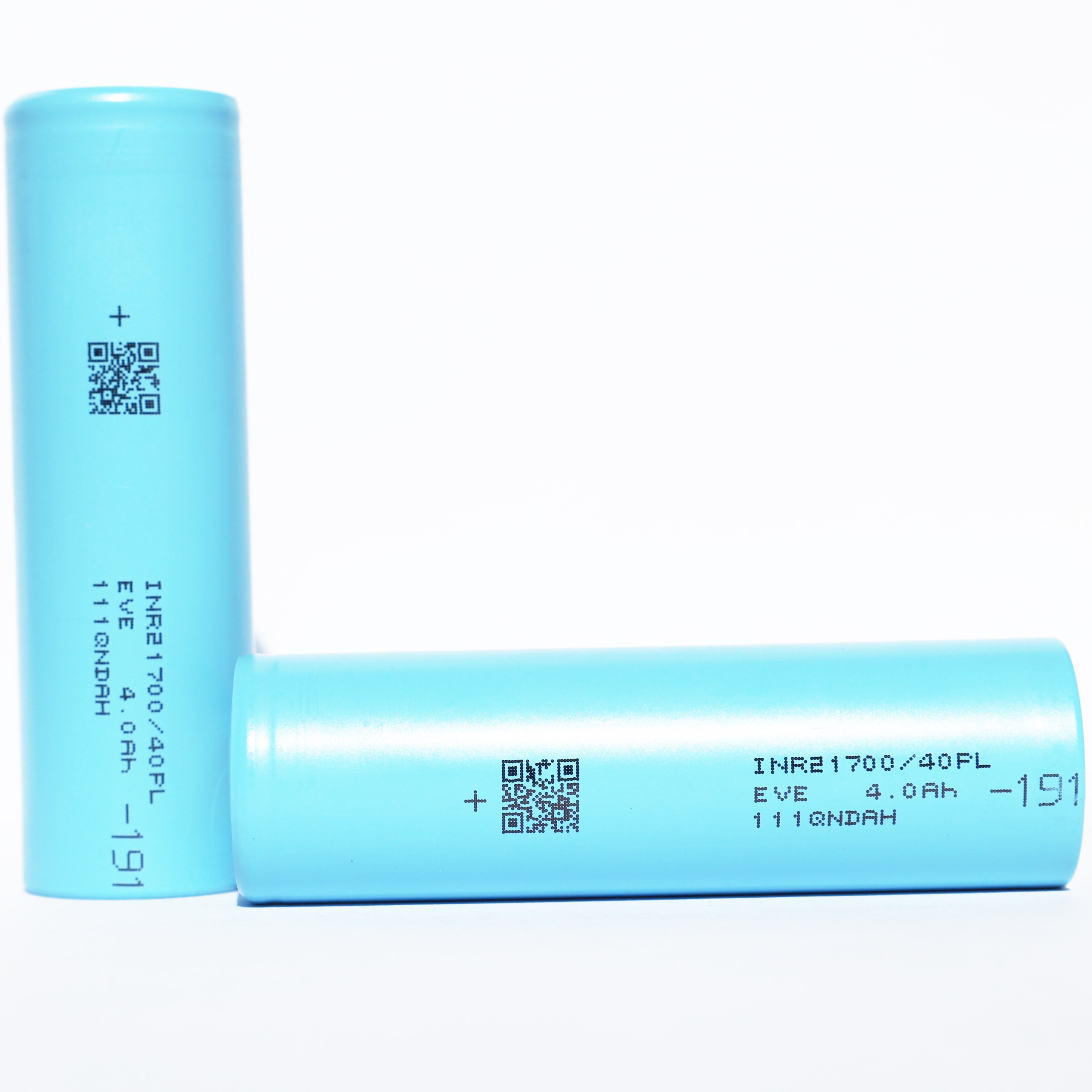
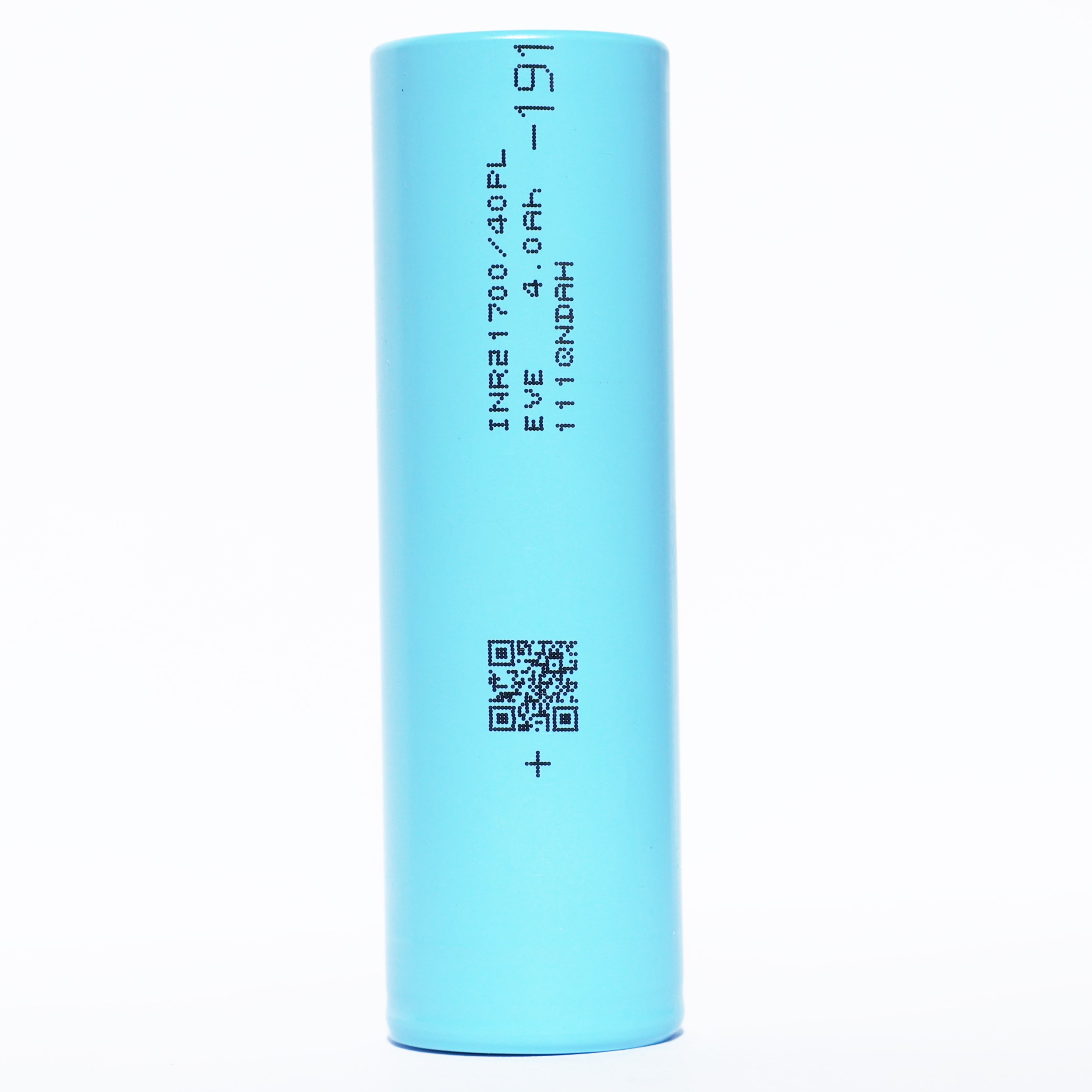
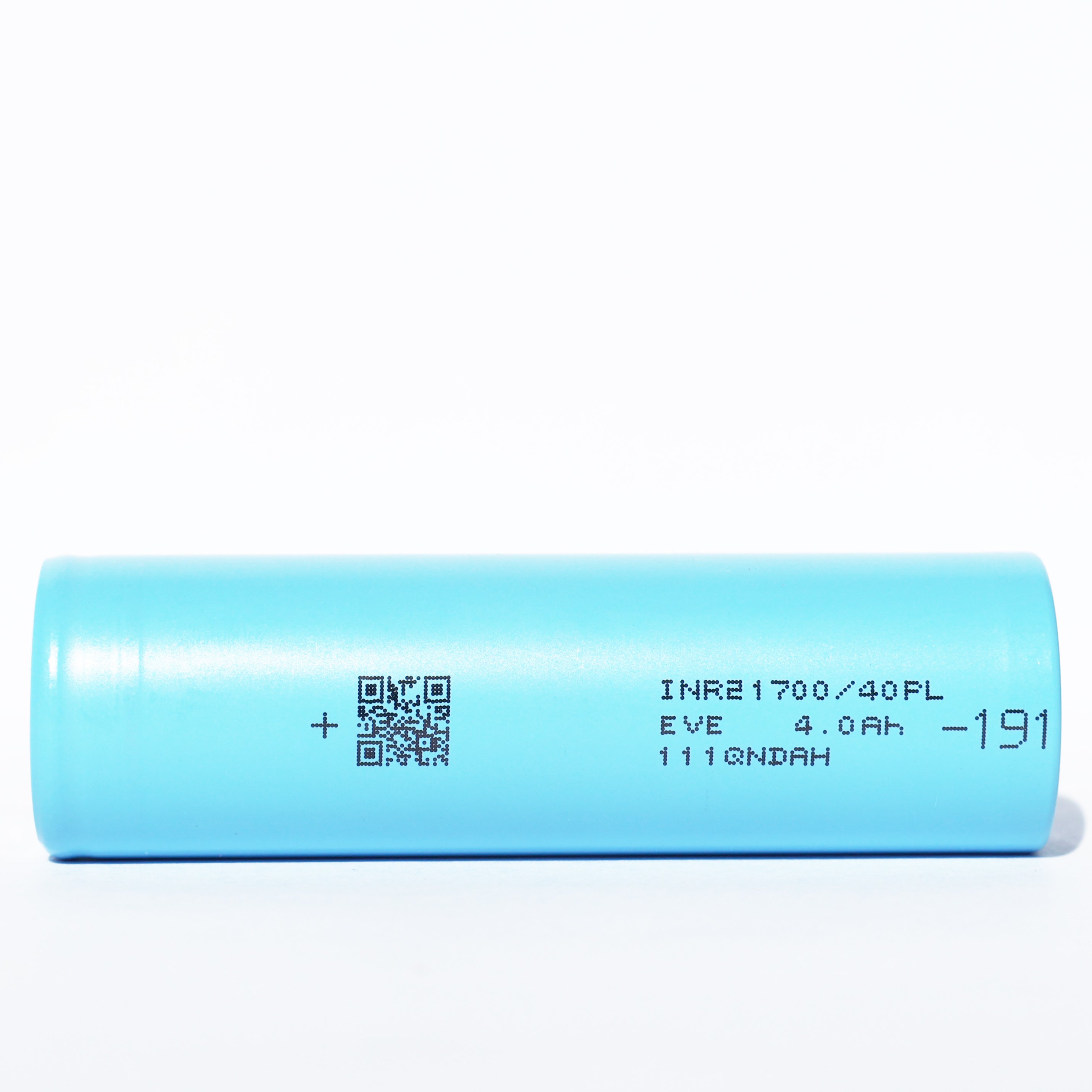
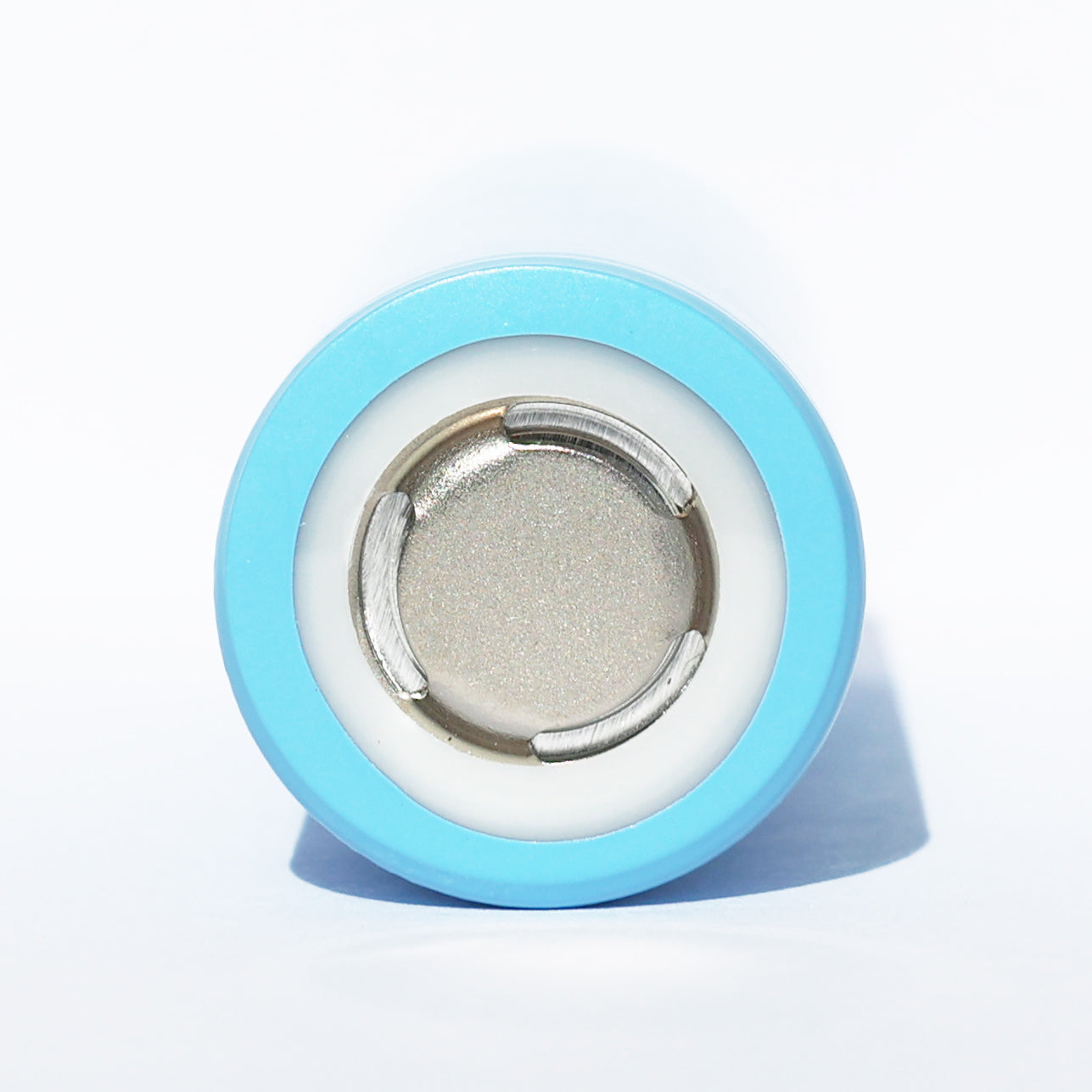


KEY SPECS · EVE ENERGY INR21700/40PL
SOURCE [1]- SIZE
- Ø21.15 × 70.15 mm
- nominal ±0.10 / ±0.15 · with tube
- CAPACITY
- Not stated by manufacturer typ.
- 4,000 mAh min.
- 0.5C to 2.50 V
- CURRENT
- Not stated by manufacturer
- continuous discharge
- TEMPERATURE
- −20 to 60 °C
- discharge · ambient
- charge 0 to 45 °C · ambient
[1] Product Specification, Lithium-ion rechargeable cell, Model INR21700/40PL, Version No. A, on file since 2024-09-18
EVE · 21700 · INR21700/40PL
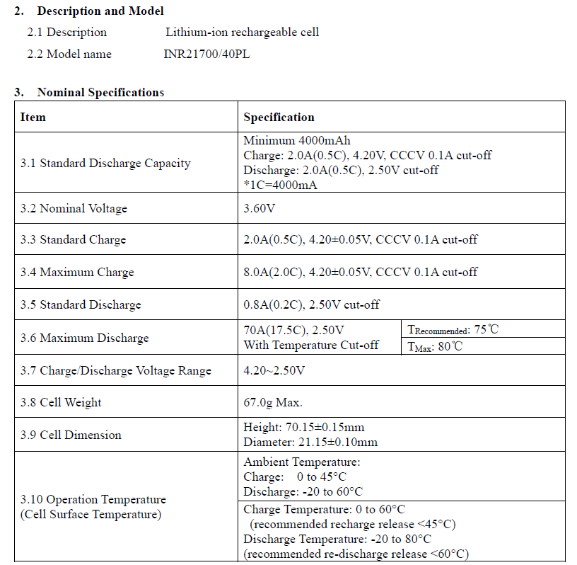
A 21700 lithium-ion cell from EVE: 4,000 mAh minimum (“Minimum 4000mAh”, at a 2.0 A (0.5C) discharge to 2.50 V) [1] §3.1. Its one discharge maximum is 70 A (17.5C), printed as “Maximum Discharge” and only “With Temperature Cut-off”: “TRecommended: 75℃”, “TMax: 80℃” [1] §3.6. EVE prints no typical capacity and calls no current continuous. It marks its specification confidential and proprietary, so we quote it but don’t link it (section 11 below). Below: the printed figures, each with its condition, and what we calculated from them, so you can check each number.
CAPACITY4,000 mAhminimum: “Minimum 4000mAh”, 2.0 A (0.5C) discharge to 2.50 V [1] §3.1; ≥ 4,000 mAh at 0.8 A (0.2C), 25 °C [1] §7.3; no typical printed
MAXIMUM DISCHARGE70 A“With Temperature Cut-off”: “TRecommended: 75℃”, “TMax: 80℃”; 17.5C, 2.50 V; not called continuous [1] §3.6
MAXIMUM CHARGE8.0 A2.0C, 4.20 ± 0.05 V CC-CV, 0.1 A cut-off, at 25 °C; standard charge 2.0 A (0.5C) [1] §3.3, §3.4, §7.2
ENERGY14.40 Whcalculated: 3.60 V nominal × 4.000 Ah minimum; [1] prints no Wh
AC IMPEDANCE≤ 5 mΩinitial, AC 1 kHz at shipping state of charge (SOC) [1] §7.4
MASS67.0 g“67.0g Max.” [1] §3.8
The library holds data sheets where the manufacturer publishes one. This cell’s specification is on file but not linked (section 11 below).
A bare cell: a component for protected packs and devices built for it. Not for vaping. Charge on a lithium-ion (Li-ion) charger that stops at 4.20 V.
01SPEC PLATE
Every printed figure, with its condition.
EVE’s data sheet for the 40PL is titled PRODUCT SPECIFICATION [1]; this page calls it the specification. Version No. A, June 2023, is the only version we hold, so the page has no version comparison. Its figures come first, copied as printed. Then the percentages its tables print, our arithmetic, and the documents we hold. Each row names its source or shows its formula.
| SPECIFICATION | VALUE | CONDITION · SOURCE |
|---|---|---|
| PRINTED · MANUFACTURER copied from specification [1] | ||
| MODEL | INR21700/40PL | as printed on every page, on the cover (“Model: INR21700/40PL”) and in §2.2 “Model name” [1]; we list the cell as EVE 40PL |
| CAPACITY, TYPICAL | Not stated | Not stated by manufacturer: [1] prints no typical, nominal or rated capacity |
| CAPACITY, MINIMUM | 4,000 mAh | “Minimum 4000mAh”; “Charge: 2.0A(0.5C), 4.20V, CCCV 0.1A cut-off”; “Discharge: 2.0A(0.5C), 2.50V cut-off”; no temperature printed in §3.1, and [1] sets 25 ± 2 °C for its tests unless otherwise specified (§6.1) [1] §3.1 |
| CAPACITY, MINIMUM, §7.3 | 4,000 mAh | “Standard Discharge Capacity ≥ 4000mAh”, with “discharge current of 0.8A (0.2C) and 2.50V cut-off at 25°C after the standard charge”; “(Referring IEC61960 standard)”; a different discharge current from §3.1, as printed; [1] doesn’t reconcile the two [1] §7.3 |
| 1C | 4,000 mA | “*1C=4000mA”: a C-rate is the current as a multiple of 4,000 mA, so 0.5C = 2.0 A and 17.5C = 70 A; every C-rate in [1] is printed beside its current [1] §3.1 |
| NOMINAL VOLTAGE | 3.60 V | “3.60V”; no condition printed [1] §3.2 |
| CHARGE VOLTAGE | 4.20 V | “4.20±0.05V”, CCCV (constant current, then constant voltage), in the Standard and Maximum Charge rows; range “4.20~2.50V” [1] §3.3, §3.4, §3.7 |
| DISCHARGE CUT-OFF | 2.50 V | “2.50V cut-off” [1] §3.1, §3.5; §3.6 prints “2.50V” without “cut-off” |
| STANDARD CHARGE | 2.0 A | “2.0A(0.5C), 4.20±0.05V, CCCV 0.1A cut-off”; defined “at 25°C for capacity” (§7.1); no charge time printed [1] §3.3 |
| MAXIMUM CHARGE | 8.0 A | “8.0A(2.0C), 4.20±0.05V, CCCV 0.1A cut-off”; defined “at 25°C” (§7.2); no temperature band and no charge time printed with it [1] §3.4 |
| STANDARD DISCHARGE | 0.8 A | “0.8A(0.2C), 2.50V cut-off” [1] §3.5 |
| MAXIMUM DISCHARGE | 70 A | “70A(17.5C), 2.50V”, “With Temperature Cut-off”: “TRecommended: 75℃”, “TMax: 80℃”; [1] doesn’t say where that temperature is read; it calls no current continuous and prints no pulse figure [1] §3.6 |
| TEMPERATURE MEASUREMENT | K-type, 30 mm up | “The temperature monitoring system (K-type thermocouple) is recommended to be placed in the middle of the cell (30mm up from the bottom of the cell), and the accuracy of the temperature monitoring system should be within ±2℃.” A separate guide clause; [1] doesn’t tie it to §3.6 [1] §12.8.7 |
| OPERATION TEMPERATURE | Two sub-rows | “3.10 Operation Temperature (Cell Surface Temperature)”: “Ambient Temperature:” “Charge: 0 to 45°C” “Discharge: -20 to 60°C”; then, with no heading of its own, “Charge Temperature: 0 to 60°C” “(recommended recharge release <45°C)” “Discharge Temperature: -20 to 80°C” “(recommended re-discharge release <60°C)”; [1] doesn’t say which basis the second sub-row has [1] §3.10 |
| AC IMPEDANCE | ≤ 5 mΩ | “Initial Internal Impedance ≤ 5mΩ”, “at AC 1kHz at shipping SOC” [1] §7.4 |
| CYCLE LIFE | ≥ 60 % of Ci | “Capacity ≥ 60%Ci” after 400 cycles: “Charge: 6.0A (1.5C) to 4.2V, CCCV 0.1A cut-off.” “Discharge: 40A (10.0C) to 2.50V or 75°C cut-off.” “Rest time: 10min after charge and 30min after discharge.” Ci is “the first discharge capacity of cycle life test at 25±2°C”; [1] doesn’t give it in mAh [1] §7.7 |
| STORAGE TEMPERATURE | −20 to 25 °C | for “1 year”; “-20~45°C” for “3 months”, “-20~60°C” for “1 month”; “(At Shipping SOC)”; Remark: recovery “more than 90% of standard discharge capacity (=4000mAh)” [1] §3.11 |
| RECOVERY AFTER 30 DAYS AT 60 °C | ≥ 3,600 mAh | “Recovery Capacity ≥ 3600mAh (90% of Standard Discharge Capacity(=4000mAh)” (one parenthesis left open, as printed); “After storage for 30days at 60℃.”; §7.8 defines Recovery Capacity as “The capacity of standard discharge of three times cycles after fully standard charged storage at condition as follows.” [1] |
| AS SHIPPED | 3.450–3.600 V | “The cell should be shipped in 3.450V to 3.600V charging voltage range.” No state of charge printed [1] §7.9 |
| LONG STORAGE | 3.50–3.80 V | for “3 months or more”: “it is strongly recommended that the cell is performed one cycle”; “the voltage of the cell is recommended from 3.50V to 3.80V”; “low-temperature (normally 0~25°C), dry and no corrosive gas” [1] §13.1 |
| DIAMETER | 21.15 mm | “Diameter: 21.15±0.10mm”; Fig. 1: “with tube” [1] §3.9 |
| HEIGHT | 70.15 mm | “Height: 70.15±0.15mm”; Fig. 1: “with tube” [1] §3.9 |
| MASS | 67.0 g | “67.0g Max.” [1] §3.8 |
| TERMINAL | Not stated | Not stated by manufacturer: [1] states no top style |
| + Source: [1] EVE Energy Co., Ltd., PRODUCT SPECIFICATION, Lithium-ion rechargeable cell, Model: INR21700/40PL, Spec. No. PBRI-INR21700/40PL-D06-01, Version No. A, June, 2023 (as printed); its revision history has one entry, A, 2023-06-02, “First Edition”; 17 pages; no validity date printed. Every page is marked “-EVE Energy CO., LTD Confidential and Proprietary-” and “EVE Confidential”, so it is quoted and cited here but not linked. Call or text to ask about it | ||
| SPECIFICATION | VALUE | CONDITION · SOURCE |
|---|---|---|
| PRINTED IN THE SPECIFICATION’S TABLES percent of “the 10A discharge capacity at 25°C”, as printed; no mAh is printed for it, so none is calculated [1] | ||
| CAPACITY AT 40 A (10.0C) | ≥ 95 % | “≥95%” of “the 10A discharge capacity at 25°C”, which [1] doesn’t give in mAh; “2.50V cut-off after the standard charge at 25°C” [1] §7.5 |
| CAPACITY AT 30 A (7.5C) | ≥ 95 % | “≥95%”; same reference and conditions [1] §7.5 |
| CAPACITY AT 0.8 A (0.2C) | ≥ 100 % | “≥100%”; same reference and conditions [1] §7.5 |
| CAPACITY AT −20 °C, 10 A | ≥ 60 % | “≥60%”, “after 3 hours storage at the test environment”, then “discharge constant current 10A (2.5C) and 2.50V cut-off after the standard charge at 25°C”; same reference [1] §7.6 |
| CAPACITY AT −10 °C, 10 A | ≥ 75 % | “≥75%”; same conditions [1] §7.6 |
| CAPACITY AT 0 °C, 10 A | ≥ 80 % | “≥80%”; same conditions [1] §7.6 |
| CAPACITY AT 60 °C, 10 A | ≥ 90 % | “≥90%”; same conditions [1] §7.6 |
| CALCULATED arithmetic on [1], shown so you can check it | ||
| ENERGY AT MINIMUM CAPACITY | 14.40 Wh | 3.60 V nominal × 4.000 Ah, the §3.1 minimum [1]; [1] prints no Wh, and we hold no SDS or UN38.3 report for this cell |
| RECOVERY AFTER §3.11 STORAGE | > 3,600 mAh | more than 90 % × 4,000 mAh, the index “(=4000mAh)” printed in the §3.11 Remark [1] |
| DIAMETER, LIMITS | 21.05–21.25 mm | 21.15 ± 0.10 mm [1] §3.9 |
| HEIGHT, LIMITS | 70.00–70.30 mm | 70.15 ± 0.15 mm [1] §3.9 |
| VOLUME | 24.6 cm³ | π × (21.15 mm ÷ 2)² × 70.15 mm ≈ 24,646 mm³, at the printed size [1] §3.9 |
| DOCUMENTED · WHAT WE HOLD the documents on file for this cell | ||
| SPECIFICATION | Version No. A | PRODUCT SPECIFICATION, Spec. No. PBRI-INR21700/40PL-D06-01, “June, 2023”; revision A, 2023-06-02, “First Edition”; the only version we hold; marked confidential and proprietary on every page, so not linked [1] |
| CHEMISTRY | Li-ion | “Lithium-ion rechargeable cell”; no cathode material printed [1] §2.1 |
| SAFETY TESTS | §8, §9 | EVE’s methods and pass criteria for seven tests; [1] prints no results (section 07 below) [1] |
| UN38.3 TEST REPORT | Not on file | we hold no UN38.3 test report or test summary for this cell; [1] §8.2 and §9.5 name UN38.3 only as the method their tests follow |
| SAFETY DATA SHEET | Not on file | we hold no safety data sheet (SDS) for this cell |
| + Source: [1] EVE Energy Co., Ltd., PRODUCT SPECIFICATION, Lithium-ion rechargeable cell, Model: INR21700/40PL, Spec. No. PBRI-INR21700/40PL-D06-01, Version No. A, June, 2023 (as printed); its revision history has one entry, A, 2023-06-02, “First Edition”; 17 pages; no validity date printed. Every page is marked “-EVE Energy CO., LTD Confidential and Proprietary-” and “EVE Confidential”, so it is quoted and cited here but not linked. Call or text to ask about it | ||
PRINTED IN [1]FIG 1.1
Voltage window
2.50 V3.60 V4.20 Vcut-offnominalcharge
Black marks: the voltages [1] prints, “2.50V cut-off” (§3.1, §3.5), “3.60V” nominal (§3.2) and “4.20±0.05V” charge (§3.3, §3.4); range “4.20~2.50V” (§3.7). Orange band: “The cell should be shipped in 3.450V to 3.600V charging voltage range.” [1] §7.9; its top equals the 3.60 V nominal voltage. For storage of 3 months or more, [1] §13.1 recommends 3.50 to 3.80 V (fig 6.3).
PRINTED IN [1]FIG 1.2
Currents, as printed
Standard Discharge “0.8A(0.2C), 2.50V cut-off” · [1] §3.5
0.8 A
Standard Charge “2.0A(0.5C), 4.20±0.05V, CCCV 0.1A cut-off”; “at 25°C for capacity” (§7.1) · [1] §3.3
2.0 A
Maximum Charge “8.0A(2.0C), 4.20±0.05V, CCCV 0.1A cut-off”; “at 25°C” (§7.2) · [1] §3.4
8.0 A
Maximum Discharge “70A(17.5C), 2.50V”, “With Temperature Cut-off”: “TRecommended: 75℃”, “TMax: 80℃” · [1] §3.6
70 A
The current rows of [1] §3 (§3.3 to §3.6), each with its printed condition; C-rates as printed, on “*1C=4000mA”. [1] calls none of them continuous and prints no pulse figure. Orange: the §3.6 “Maximum Discharge”, its only maximum discharge figure, which carries a temperature cut-off; [1] doesn’t say where that temperature is read (fig 4.2).
PRINTED IN [1]FIG 1.3
Operation temperature, as printed
“Charge: 0 to 45°C” sub-row headed “Ambient Temperature:” · [1] §3.10
“Discharge: -20 to 60°C” sub-row headed “Ambient Temperature:” · [1] §3.10
“Charge Temperature: 0 to 60°C” “(recommended recharge release <45°C)” · second sub-row, no heading of its own · [1] §3.10
“Discharge Temperature: -20 to 80°C” “(recommended re-discharge release <60°C)” · second sub-row · [1] §3.10
Maximum Discharge cut-off “TRecommended: 75℃”, “TMax: 80℃” · [1] §3.6
One row of [1], quoted whole, in °C. Its label reads “3.10 Operation Temperature (Cell Surface Temperature)”; the first sub-row (black) is headed “Ambient Temperature:”, the second (gray) has no heading of its own, and [1] doesn’t say which basis the second has. We label neither sub-row beyond its printed words. Marks: the second sub-row’s release temperatures, and the §3.6 cut-off temperatures.
PRINTED IN [1]FIG 1.4
Storage temperature, by duration
For 1 month “-20~60°C” “(At Shipping SOC)”
For 3 months “-20~45°C” “(At Shipping SOC)”
For 1 year “-20~25°C” “(At Shipping SOC)”
“3.11 Storage Temperature (At Shipping SOC)”, by duration; orange: the 1-year range. Below the table, [1] prints “Remark: The Recovery capacity is more than 90% of standard discharge capacity (=4000mAh) after storage at the condition of 3.11.” That is more than 3,600 mAh: 90 % × 4,000 mAh, our arithmetic. [1] says cells ship at 3.450 to 3.600 V (§7.9) and prints no percentage for “Shipping SOC”.
PRINTED IN [1]FIG 1.5
Minimum capacity, printed twice
Bars start at zero. [1] prints the same 4,000 mAh minimum twice, with different discharge currents. §3.1: “Minimum 4000mAh”, “Charge: 2.0A(0.5C), 4.20V, CCCV 0.1A cut-off”, “Discharge: 2.0A(0.5C), 2.50V cut-off”. §7.3: “Standard Discharge Capacity ≥ 4000mAh”, with “discharge current of 0.8A (0.2C) and 2.50V cut-off at 25°C after the standard charge” “(Referring IEC61960 standard)”. [1] doesn’t reconcile the two, so this page quotes both. It prints no typical, nominal or rated capacity.
CALCULATED FROM [1]FIG 1.6
Energy, calculated
Bars start at zero. [1] prints no energy figure, and we hold no SDS or UN38.3 report for this cell. 14.40 Wh = 3.60 V nominal (§3.2) × 4.000 Ah, the §3.1 minimum capacity: our arithmetic, an estimate at the minimum capacity, not a printed figure.
02 · CAPACITY
At least 95 % of its 10 A capacity at 40 A.
[1] §7.5 prints the capacity at four currents, from 0.8 A (0.2C) to 40 A (10.0C), as a percent of “the 10A discharge capacity at 25°C”, which it doesn’t give in mAh. At 30 and 40 A it prints “≥95%”. Above 40 A it prints no capacity: its “Maximum Discharge” of 70 A, “With Temperature Cut-off”: “TRecommended: 75℃”, “TMax: 80℃” [1] §3.6, has no capacity, runtime or cycle figure beside it.
10 A · 2.5C100 %the reference, “the 10A discharge capacity at 25°C”; no mAh printed [1] §7.5
40 A · 10.0C≥ 95 %“≥95%” printed in [1] §7.5; “2.50V cut-off after the standard charge at 25°C”
PRINTED IN [1]FIG 2.1
%
60708090100010203040506070 A≥100%100%≥95%≥95%70 A §3.6 “Maximum Discharge”, “With Temperature Cut-off”: no capacity printed
Discharge current, A
Data: [1] §7.5, Discharge Rate Capabilities · “2.50V cut-off after the standard charge at 25°C” · percent of “the 10A discharge capacity at 25°C”, printed “≥” except at 10 A · points only: EVE prints no curve between them · the vertical line marks the §3.6 “Maximum Discharge”, 70 A, “With Temperature Cut-off”: “TRecommended: 75℃”, “TMax: 80℃” · axis starts at 60 % · data table under fig 3.1
03BY CURRENT
Capacity, by current.
[1] §7.5 prints the capacity at 0.8, 10, 30 and 40 A as a percent of “the 10A discharge capacity at 25°C”. It prints no mAh for that reference, so this page gives the percentages only and calculates no runtime from them. Its 70 A “Maximum Discharge”, “With Temperature Cut-off” [1] §3.6, has no capacity figure.
PRINTED IN [1]FIG 3.1
Capacity, by discharge current
Capacity to 2.50 V after the standard charge at 25 °C, printed in [1] §7.5 as a percent of the capacity at 10 A. Its note reads “Note: Relative capacity is divided the 10A discharge capacity at 25°C.” (as printed; the §7.6 note reads “is divided by the”). [1] gives that 10 A capacity no mAh figure, so none is calculated. Bars start at zero and show the printed figure, a lower bound (“≥”) except at 10 A. Orange: 40 A, the largest current with a printed capacity; none is printed at 70 A (§3.6 “Maximum Discharge”, “With Temperature Cut-off”).
DATA TABLE · FIG 3.1 · AS PRINTED
| CURRENT | RATE | RELATIVE CAPACITY |
|---|---|---|
| 0.8A | 0.2C | ≥100% |
| 10A | 2.5C | 100% |
| 30A | 7.5C | ≥95% |
| 40A | 10.0C | ≥95% |
| 70A (§3.6) | 17.5C | not printed |
PRINTED IN [1]FIG 3.2
Discharge currents in the specification
Standard Discharge, §3.5 “0.8A(0.2C), 2.50V cut-off”; also the §7.3 capacity discharge
Capacity, §3.1 “Discharge: 2.0A(0.5C), 2.50V cut-off”
Rate table, §7.5 “0.8A”, “10A”, “30A”, “40A” (0.2C, 2.5C, 7.5C, 10.0C); “2.50V cut-off after the standard charge at 25°C”
Temperature table, §7.6 “discharge constant current 10A (2.5C)”, at −20 to 60 °C
Cycle-life test, §7.7 “Discharge: 40A (10.0C) to 2.50V or 75°C cut-off.”
Maximum Discharge, §3.6 “70A(17.5C), 2.50V”, “With Temperature Cut-off”: “TRecommended: 75℃”, “TMax: 80℃”
Where each discharge current in [1] sits, on one 0–80 A scale; currents and C-rates as printed. §3.5 “Standard Discharge” and §3.6 “Maximum Discharge” are current rows of the §3 table; the rest are test conditions, including the discharge of the §3.1 capacity condition. [1] prints a capacity for currents from 0.8 to 40 A (fig 3.1) and none at 70 A, and calls no current continuous.
What 70 A means
- In plain terms: 70 A is the most current [1] lists, and it lists it only with a temperature cut-off, so the discharge has to stop when that temperature is reached: 75 °C recommended, 80 °C at most (§3.6). [1] prints no maximum without the cut-off, and its §11 Note 3 asks customers to discuss the equipment design with EVE in advance and to “consult about the high rate current, maximum charge and special application” in the same way.
- [1] prints one maximum discharge current, under “Maximum Discharge”: “70A(17.5C), 2.50V”, “With Temperature Cut-off”, with “TRecommended: 75℃” and “TMax: 80℃” beside it [1] §3.6. It prints no duration with it, and no figure without the cut-off.
- [1] doesn’t say where the cut-off temperature is read. Its guide separately recommends that “The temperature monitoring system (K-type thermocouple)” be placed “in the middle of the cell (30mm up from the bottom of the cell)”, accurate “within ±2℃” [1] §12.8.7. It doesn’t tie that clause to §3.6.
- No current in [1] is called continuous, and no pulse figure is printed. Its guide says “The cell shall be discharged continuously at less than maximum discharging current specified in the specification.” and that a higher current “shall be discussed with EVE” [1] §12.3.1. That sets a ceiling, not a continuous rating.
- 40 A is the largest current with a printed capacity: “≥95%” of the 10 A capacity at 25 °C [1] §7.5. The 400-cycle figure also discharges at 40 A, “to 2.50V or 75°C cut-off” [1] §7.7. [1] prints no capacity and no cycle figure at 70 A.
04TEMPERATURE
Capacity in the cold and the heat.
One table in [1] §7.6: capacity at −20, −10, 0, 25 and 60 °C, each after a standard charge at 25 °C and 3 hours at the test temperature, with a 10 A (2.5C) discharge to 2.50 V, as a percent of the 10 A capacity at 25 °C. At −20 °C it prints “≥60%”. [1] prints no charge-temperature table.
PRINTED IN [1]FIG 4.1
Capacity, by discharge temperature
Capacity at each temperature, printed in [1] §7.6 as a percent of the 10 A capacity at 25 °C: “after 3 hours storage at the test environment”, then “discharge constant current 10A (2.5C) and 2.50V cut-off after the standard charge at 25°C”. Its note: “Note: Relative capacity is divided by the 10A discharge capacity at 25°C.” [1] gives that capacity no mAh figure, so none is calculated. Bars start at zero and show the printed figure, a lower bound (“≥”) except at 25 °C. Orange: below 0 °C. −20 °C, the coldest point printed, is the bottom of both discharge ranges in §3.10.
DATA TABLE · FIG 4.1 · AS PRINTED
| TEMPERATURE | RELATIVE CAPACITY |
|---|---|
| -20°C | ≥60% |
| -10°C | ≥75% |
| 0°C | ≥80% |
| 25°C | 100% |
| 60°C | ≥90% |
PRINTED IN [1]FIG 4.2
Discharge temperatures and cut-offs
“Discharge: -20 to 60°C” sub-row headed “Ambient Temperature:” · [1] §3.10
“Discharge Temperature: -20 to 80°C” “(recommended re-discharge release <60°C)” · second sub-row · [1] §3.10
Maximum Discharge, §3.6 “With Temperature Cut-off”: “TRecommended: 75℃”, “TMax: 80℃”
Cycle-life test, §7.7 40 A (10.0C) discharge “to 2.50V or 75°C cut-off”
Capacity table, §7.6 test points −20, −10, 0, 25 and 60 °C, at 10 A
Discharge temperatures in [1], on one −20 to 90 °C scale. Black: the §3.10 sub-row headed “Ambient Temperature:”; gray: the unheaded second sub-row, with its release mark at 60 °C. Marks: the §3.6 cut-off temperatures, the 75 °C cut-off of the §7.7 cycle test, and the §7.6 test points. [1] doesn’t say where the §3.6 and §7.7 temperatures are read; §12.8.7, a separate clause, recommends a K-type thermocouple 30 mm up from the bottom of the cell.
What the table leaves out
- No capacity above 60 °C, though the second sub-row of §3.10 prints “Discharge Temperature: -20 to 80°C” with “(recommended re-discharge release <60°C)” [1].
- No capacity at a high current in the cold: §7.6 uses a 10 A discharge only [1].
- No charge-temperature table: [1] prints no capacity after a charge at any temperature but 25 °C.
- Its operating temperatures are one row, printed “3.10 Operation Temperature (Cell Surface Temperature)”; the first sub-row is headed “Ambient Temperature:” and the second has no heading. [1] doesn’t say which basis the second has (fig 1.3).
05CHARGING
Charging: 2.0 A standard, 8.0 A maximum.
The specification prints a “Standard Charge” of “2.0A(0.5C), 4.20±0.05V, CCCV 0.1A cut-off” and a “Maximum Charge” of “8.0A(2.0C), 4.20±0.05V, CCCV 0.1A cut-off”; §7.1 and §7.2 define both at 25 °C [1]. It prints no charge time. Its 400-cycle figure charges at 6.0 A (1.5C), and both §3.10 charge ranges start at 0 °C.
PRINTED IN [1]FIG 5.1
Charge currents, as printed
Charge currents as [1] prints them: “2.0A(0.5C), 4.20±0.05V, CCCV 0.1A cut-off” (§3.3), “Charge: 6.0A (1.5C) to 4.2V, CCCV 0.1A cut-off.” (§7.7) and “8.0A(2.0C), 4.20±0.05V, CCCV 0.1A cut-off” (§3.4); C-rates as printed. Orange: the “Maximum Charge”. [1] prints no charge time for any of them. Its overcharge test, 12.0 A (3C) at 4.6 V (§9.1), is an abuse condition, not a limit (section 07 below).
PRINTED IN [1]FIG 5.2
Charge temperature, as printed
“Charge: 0 to 45°C” sub-row headed “Ambient Temperature:” · [1] §3.10
“Charge Temperature: 0 to 60°C” “(recommended recharge release <45°C)” · second sub-row, no heading of its own · [1] §3.10
Standard and Maximum Charge defined “at 25°C” · [1] §7.1, §7.2
Where [1] allows charging, in °C. Black: “Charge: 0 to 45°C” in the §3.10 sub-row headed “Ambient Temperature:”; gray: “Charge Temperature: 0 to 60°C” in the unheaded second sub-row, with its “(recommended recharge release <45°C)” marked. Both start at 0 °C: below 0 °C, don’t charge. [1] prints no capacity after a charge at any temperature but 25 °C.
Before you charge
- Use a lithium-ion charger with a CC-CV profile that stops at 4.20 V: [1] prints “4.20±0.05V”, CCCV, with a 0.1 A cut-off [1] §3.3, §3.4.
- 2.0 A (0.5C) is the “Standard Charge” and 8.0 A (2.0C) the “Maximum Charge”, both defined at 25 °C [1] §3.3, §3.4, §7.1, §7.2. [1]’s guide says “Charging current shall be less than maximum charge current specified in the specification.” [1] §12.2.1. The 400-cycle figure charges at 6.0 A (1.5C) [1] §7.7.
- Charge within §3.10: “Charge: 0 to 45°C” under “Ambient Temperature:”, and “Charge Temperature: 0 to 60°C” with “(recommended recharge release <45°C)” in the unheaded second sub-row [1]. Below 0 °C, don’t charge.
- [1] prints no charge time, no pre-charge level and no minimum voltage for starting a charge. Its guide asks for a device that stops discharge at the cut-off voltage, and a charger that detects the cell voltage to decide how to recharge [1] §12.3.3.
- In a pack, a BMS (battery management system) should end charge at 4.20 V per cell; [1] asks for a device to monitor “each voltage of cell block” and a warning system for over temperature, over voltage and over current [1] §12.6.6.
Figs 5.1 and 5.2 plot values [1] prints as text; EVE draws no chart of them. [1] prints the charge temperatures in two sub-rows of §3.10, quoted whole in fig 1.3; we label neither beyond its printed words.
06CYCLE LIFE AND STORAGE
What it keeps after cycling, and recovers after storage.
[1] specifies a “Recovery Capacity” of at least 3,600 mAh after 30 days at 60 °C from full charge (§7.8). That is the capacity on standard discharge cycles after the storage, not the charge left in the cell, and [1] prints no self-discharge figure. After 400 cycles of “Charge: 6.0A (1.5C) to 4.2V, CCCV 0.1A cut-off.” and “Discharge: 40A (10.0C) to 2.50V or 75°C cut-off.” it specifies “Capacity ≥ 60%Ci” (§7.7), where Ci is the test’s own first discharge capacity, which [1] doesn’t give in mAh. It prints no cycle-life curve. Its storage clauses, in §3.11, §12.4 and §13.1, are each worded differently (fig 6.2).
PRINTED + CALC. · [1]FIG 6.1
Capacity after storage and cycling
Capacity after storage and cycling as [1] prints it, in mAh where [1] gives one. New: “Minimum 4000mAh” at a 2.0 A (0.5C) discharge (§3.1) and “≥ 4000mAh” at 0.8 A (0.2C), 25 °C (§7.3). After 30 days at 60 °C from full charge, §7.8 prints “≥ 3600mAh” (“After storage for 30days at 60℃.”); it defines Recovery Capacity as “The capacity of standard discharge of three times cycles after fully standard charged storage at condition as follows.” Gray: after storage at the §3.11 conditions, “more than 90%” of the “(=4000mAh)” index, more than 3,600 mAh by our arithmetic. After 400 cycles of “Charge: 6.0A (1.5C) to 4.2V, CCCV 0.1A cut-off.” and “Discharge: 40A (10.0C) to 2.50V or 75°C cut-off.”, with “Rest time: 10min after charge and 30min after discharge.”: “Capacity ≥ 60%Ci”. Ci, the test’s first discharge capacity at 25 ± 2 °C, isn’t printed in mAh, so there is no bar. A specification, not a warranty, and not a curve: [1] prints no capacity between cycle 1 and 400.
PRINTED IN [1]FIG 6.2
Storage temperature, every statement
1 year, §3.11 “-20~25°C” “(At Shipping SOC)”
3 months, §3.11 “-20~45°C” “(At Shipping SOC)”
1 month, §3.11 “-20~60°C” “(At Shipping SOC)”
Long storage, §13.1 3 months or more: “low-temperature (normally 0~25°C), dry and no corrosive gas”
Recovery test, §7.8 “After storage for 30days at 60℃.”
[1]’s storage statements, each in its own words, on one −20 to 80 °C scale. Orange: the 1-year range in §3.11. Gray: §13.1’s advice for 3 months or more, which also recommends one cycle and a cell voltage of 3.50 to 3.80 V (fig 6.3). The §7.8 mark is a 30-day test at 60 °C, not storage advice. §12.4.1 asks for storage “within a range of temperatures specified in the specification”.
PRINTED IN [1]FIG 6.3
Storage voltage, as printed
As shipped, §7.9 “3.450V to 3.600V charging voltage range”
Long storage, §13.1 “from 3.50V to 3.80V”, for 3 months or more
Nominal voltage, §3.2 “3.60V”
Storage voltage as [1] prints it, on a 3.4–3.9 V scale. The shipping range (§7.9) and the long-storage range (§13.1) overlap from 3.50 to 3.60 V. [1] prints no state of charge for either. §12.4.2 asks for long-term storage “at lower voltage within a range specified in the specification”.
07SAFETY TESTS
The specification’s own safety tests.
Sections 8 and 9 of [1] set seven tests for the cell, each with EVE’s method and pass criterion; [1] prints no results. We hold no UN38.3 test report or test summary and no safety data sheet (SDS) for the 40PL, so this page shows no transport-test results. Two of the methods name UN38.3 as the standard they follow: a test method, not a report.
| TEST | METHOD, CONDENSED FROM [1] | PASS CRITERION, AS PRINTED | METHOD REFERENCE, AS PRINTED | SECTION |
|---|---|---|---|---|
| Free Fall Test | Each fully charged cell dropped 3 times from 1.0 m onto a concrete floor, in random orientations; 1 h of rest, then a visual inspection | “No fire, no explosion.” | “Free fall test is according to the IEC62133 standard.” | [1] §8.1 |
| Vibration Test | For the X and Y axes of the cylindrical cell: 7 Hz → 200 Hz → 7 Hz in 15 min, repeated 12 times, 3 h in total; 1 g from 7 to 18 Hz, then 1.6 mm amplitude, at most 8 g, to 200 Hz | “No fire, no explosion, no leakage, with less than 10% of OCV drop.” | “Vibration test is according to the UN38.3 standard.” | [1] §8.2 |
| Overcharge Test | Fully discharged (standard discharge) cell charged at 4.6 V and 12.0 A (3C) for 7 h | “No fire, no explosion.” | “Overcharge test is according to the UL1642 standard.” | [1] §9.1 |
| External Short-circuit Test | Fully charged (standard charge) cell shorted through an 80 ± 20 mΩ load at 55 ± 5 °C, for 24 h or until the surface temperature has fallen by 20 % of its maximum rise, whichever is sooner | “No fire, no explosion.” | “External short-circuit test is according to the IEC62133 standard.” | [1] §9.2 |
| Forced Discharge Test | Discharged cell reverse-charged at 4.0 A (1C) for 90 min | “No fire, no explosion.” | “Forced discharge test is according to the IEC62133 standard.” | [1] §9.3 |
| Heating Test | Standard-charged cell heated at 5 °C per minute to 130 °C, then held 10 min in an oven | “No fire, no explosion.” | “Heating test is according to the UL1642 standard.” | [1] §9.4 |
| Low Pressure Test | Fully charged (standard charge) cell stored at 11.6 kPa or less for at least 6 h at ambient temperature | “No fire, no explosion and no leakage with less than 10% of OCV drop.” | “Low pressure test is according to the UN38.3 standards.” | [1] §9.5 |
Methods condensed in our words from sections 8 and 9 of [1], without adding or dropping a figure; criteria and method references quoted as printed. These are EVE’s methods and pass criteria for the cell; [1] prints no results, and the standards it names are the methods its tests follow, not certificates. We hold no certificate or test report for the 40PL. Their voltages and currents, such as 4.6 V and 12.0 A (3C) in the overcharge test, are abuse conditions, not limits. OCV: open-circuit voltage.
08COMPARE
Where the 40PL sits.
Fifteen other 21700 cells, each from its own data sheet or specification. The 40PL’s 70 A is printed as a “Maximum Discharge”, “With Temperature Cut-off”, not as a continuous rating; every other discharge figure in the chart is printed as continuous, except the Molicel M65A’s, whose sheet prints no rating type. So the 40PL’s bar doesn’t compare like for like: the next two, the Tenpower 60XG and the Molicel P50B, are 60 A continuous ratings with temperature cut-offs of 75 and 80 °C. In the chart, no cell shows a lower minimum capacity than the 40PL’s 4,000 mAh; the Samsung 40T, Molicel P42A and Sony/Murata VTC6A show the same, each at its own condition. The 40T’s sheet also prints a “Rated discharge capacity” minimum of 3,900 mAh at 10 A; [1] gives the 40PL no mAh figure at 10 A. The conditions behind each figure differ, so the table quotes each sheet’s wording.
DATA SHEETS · [1][2]FIG 8.1
Minimum capacity and discharge, side by side
- EVE 40PL INR21700/40PL4,000 mAh minimum · no typical printed70 A “Maximum Discharge”, not called continuous · “With Temperature Cut-off”: “TRecommended: 75℃”, “TMax: 80℃”
- Tenpower 60XG INR21700-60XG5,900 mAh minimum · 6,000 nominal60 A continuous · 75 °C temp. cut-off; 40 A without
- Molicel P50B INR-21700-P50B4,850 mAh minimum · 5,000 typical60 A continuous · 80 °C cut-off
- Samsung 45T CC4503F1014,400 mAh minimum · 4,500 typical50 A continuous · 80 °C temp. cut; 35 A without
- Samsung 50S INR21700-50S4,800 mAh rated minimum at 10 A · 5,000 typical45 A continuous · 80 °C temp. cut; 25 A without
- Molicel P45B INR-21700-P45B4,350 mAh minimum · 4,500 typical45 A max. continuous · no condition printed
- Samsung 40T INR21700-40T4,000 mAh minimum · no typical printed45 A continuous · 80 °C temp. cut; 35 A without
- Molicel P42A INR-21700-P42A4,000 mAh minimum · 4,200 typical45 A continuous · no condition printed
- Sony/Murata VTC6A US21700VTC6A4,000 mAh minimum · 4,160 nominal40 A continuous max. · 80 °C temp. cut
- Molicel M65A 21700-M65A6,400 mAh minimum · 6,500 ± 70 at 0.2C; no typical label25.6 A rating type not printed · 90 °C cut-off; preliminary
- EVE 50E INR21700/50E4,900 mAh minimum · 5,000 nominal15 A continuous · no condition printed
- Molicel M50A INR-21700-M50A4,800 mAh minimum · 5,000 typical15 A continuous · no condition printed
- Samsung 50G INR21700-50G (Ver. B)4,900 mAh minimum · no typical printed14.7 A for continuous discharge · −20 to 30 °C; 9.8 A at 31 to 60 °C
- LG M50LT INR21700M50LTMinimum not stated by manufacturer · no mAh capacity printed14.4 A max. continuous · 10 to 25 °C; 7.2 A at 25 to 55 °C, 2.4 A at −20 to 10 °C
- Samsung 58E CC5493F101 (Ver. A)5,330 mAh minimum · no typical printed10.66 A 2C for continuous discharge · 10.66 A = 2 × 5,330 mA, our arithmetic
- Samsung 50E INR21700-50E4,900 mAh minimum · no typical printed9.8 A for continuous discharge · no condition printed
Each cell’s figures copied from its own data sheet or specification [1][2]. Bars start at zero: minimum capacity on a 0–7,000 mAh scale, discharge on 0–70 A. The condition sits beside each current; where a sheet prints two continuous figures, the bar shows the higher and the condition names the other. Orange: the EVE 40PL. Its 70 A is printed as a “Maximum Discharge”, “With Temperature Cut-off”, and is not called continuous; the other figures are printed as continuous, except the M65A’s, whose sheet prints no rating type. The 50S’s 4,800 mAh is its rated minimum at 10 A; the 58E’s 10.66 A is our arithmetic, 2 × 5,330 mA. Pulse figures, and the non-continuous figures some sheets print beside a continuous one, are left out; the 40PL’s 70 A maximum is shown because it is the only discharge figure [1] prints.
| CELL | TYPICAL OR NOMINAL mAh | MINIMUM mAh | DISCHARGE AS PRINTED | CHARGE AS PRINTED | MASS g |
|---|---|---|---|---|---|
| EVE 40PL INR21700/40PL |
not printed | 4,000 | “Maximum Discharge” “70A(17.5C), 2.50V”, “With Temperature Cut-off”: “TRecommended: 75℃”, “TMax: 80℃” [1] §3.6 (no current is called continuous; no pulse figure printed) | “Maximum Charge” “8.0A(2.0C), 4.20±0.05V, CCCV 0.1A cut-off”; “Standard Charge” “2.0A(0.5C), 4.20±0.05V, CCCV 0.1A cut-off” [1] §3.3, §3.4 | 67.0 “67.0g Max.” |
|
Tenpower 60XG INR21700-60XG |
6,000 nominal | 5,900 | “Max. continuous discharge current: 40A (without temperature cut off) / 60A(with 75℃ temperature cut-off)” | “Max. charging current: 16A” (no condition printed) | 76.0 max |
|
Molicel P50B INR-21700-P50B |
5,000 typical | 4,850 | “Discharge Current, Continuous: 60 A (80°C cut-off)” | “Charge Current, Maximum: 25 A (70°C cut-off)” | 71 max |
|
Samsung 45T CC4503F101 |
4,500 typical | 4,400 | “Max. continuous discharge (Surface temperature): 35A(Without temperature cut) / 50A(With 80℃ temperature cut)” | “Max. charge current: 9A (for step charge) / 6A (continuous charge)” | 72.0 max |
|
Samsung 50S INR21700-50S |
5,000 typical | 4,800 rated minimum at 10 A | “Max. continuous discharge (Surface temperature): 25A(Without temperature cut) / 45A(With 80℃ temperature cut)” | “Max. charge current: 6A (continuous charge)” | 72.0 max |
|
Molicel P45B INR-21700-P45B |
4,500 typical | 4,350 | “Maximum continuous discharging current: 45A” (no condition printed; remark: “Cycle life is reduced at high rates.”) | “Maximum continuous charging current: 9A” (remark: “High rate charge cycle will decay fast.”) | 70 max |
|
Samsung 40T INR21700-40T |
not printed | 4,000 | “Max. continuous discharge (Surface temperature): 35A(Without temperature cut) / 45A(With 80℃ temperature cut)” | “Rated charge: CCCV, 6A, 4.20 V, 100mA cut-off” (this spec prints no separate Max. charge current item) | 70 max |
|
Molicel P42A INR-21700-P42A |
4,200 typical | 4,000 | “Discharge Current, Continuous: 45 A” (no condition printed) | not printed on the Version 1.7 sheet (“Charge Current, Standard: 4.2 A”); Doc # INR21700P42A-01 Rev. 0.2: “Maximum charging current: 8.4A, See Section 4.14” | 70 max |
| Sony/Murata VTC6A US21700VTC6A |
4,160 nominal | 4,000 | “Continuous Maximum Discharging Current: 40A (With 80deg.C temperature cut)” | “Maximum Charging Current: 6A (Continuous)” | not printed placeholder “xx ±1.5g” |
| Molicel M65A 21700-M65A |
6,500 “Capacity (0.2C): 6500 mAh ± 70 mAh”; no typical or nominal label printed | 6,400 | “Discharge current: 25.6A (90℃cut-off)” (the word continuous is not printed; preliminary R&D data) | “Charge current: 6.5A (Standard) / 6.5A (Max)” | 72.5 ± 1.5, as printed |
|
EVE 50E INR21700/50E |
5,000 nominal | 4,900 | “Max Continuous Discharge current: 15000 mA” (no condition printed) | “Max. Continuous Charge current: 2500 mA” (§5.9); “Charging Temp.” 15~50 °C: “≤5000mA” (§5.12); “Charge rates greater than 5000mA are not recommended.” (§12.2.1 b) | 69.0 ± 2.0, as printed |
| Molicel M50A INR-21700-M50A |
5,000 typical | 4,800 | “Discharge Current, Continuous: 15 A” (no condition printed) | not printed on the V3 data sheet (“Charge Current, Standard: 2.5 A”); Doc # INR21700M50A-01 Rev. 0.1: “Maximum charging current: 5.0A” | 70 max |
| Samsung 50G INR21700-50G (Ver. B) |
not printed | 4,900 | “Max. Discharge Current (*²): 3C (14,700mA, for continuous discharge @ -20℃~30℃) / 2C (9,800mA, for continuous discharge @ 31℃~60℃)” | “Max. Charge Current: 4,900mA (not for cycle life)” | 71 max |
| LG M50LT INR21700M50LT |
not printed no mAh capacity printed; energy 18.2 Wh nominal, 17.6 Wh minimum | Not stated by manufacturer | “Max. Discharge Current (complete full charge)²⁾: -20 ~ 10℃ 0.5C (2,400mA) / 10 ~ 25℃ 3.0C(14,400mA) / 25 ~ 55℃ 1.5C(7,200mA)” (the sheet’s note 2 calls these the maximum continuous currents) | “Max. Charge Current (complete full charge)²⁾: 0 ~ 25℃ 0.3C (1,440mA) / 25 ~ 45℃ 0.7C (3,360mA)” | 68.2 ± 1.0, with tube and washer |
|
Samsung 58E CC5493F101 (Ver. A) |
not printed | 5,330 | “Max. Discharge Current (*²): 2C (for continuous discharge)”; “*1C=5,330 mA” (non-continuous figure not shown; 10.66 A = 2 × 5,330 mA is our arithmetic) | “Max. Charge Current: 1C (not for cycle life)”; “*1C=5,330 mA” | 74 max |
|
Samsung 50E INR21700-50E |
not printed | 4,900 | “Max. Discharge Current: 9,800mA (for continuous discharge)” (non-continuous figure not shown) | “Max. Charge Current: 4,900mA (not for cycle life)” | 69.5 max |
Text in quotation marks is copied as printed from each manufacturer data sheet or specification [1][2], newest version in our files, checked by a second reading; notes in parentheses are ours. Several of these sheets are marked draft, tentative, preliminary or confidential; Sources gives each version as printed. Links go to the bare-cell listing in our store; cells without a link aren’t listed there.
09PACK MATH
From one cell to a pack.
How the single-cell figures scale in series (S) and parallel (P). Illustrative arithmetic, not a pack rating.
V MAX4.20 × S
charge voltage, “4.20±0.05V” [1] §3.3, §3.4
V NOMINAL3.60 × S
nominal voltage, “3.60V” [1] §3.2
CAPACITY4.0 × P
Ah, “Minimum 4000mAh” [1] §3.1
MAXIMUM70 × P
A: the §3.6 “Maximum Discharge”, “With Temperature Cut-off”, times P*; not continuous
| CONFIG | CELLS | V MAX | V NOMINAL | Ah MINIMUM | Wh AT MINIMUM Ah | MAXIMUM A, CALCULATED* | CELL MASS g, MAX |
|---|---|---|---|---|---|---|---|
| 1S1P | 1 | 4.20 | 3.60 | 4.00 | 14.4 | 70 | 67.0 |
| 2S1P | 2 | 8.40 | 7.20 | 4.00 | 28.8 | 70 | 134.0 |
| 3S1P | 3 | 12.60 | 10.80 | 4.00 | 43.2 | 70 | 201.0 |
| 4S1P | 4 | 16.80 | 14.40 | 4.00 | 57.6 | 70 | 268.0 |
| 2S2P | 4 | 8.40 | 7.20 | 8.00 | 57.6 | 140 | 268.0 |
| 3S2P | 6 | 12.60 | 10.80 | 8.00 | 86.4 | 140 | 402.0 |
| 4S2P | 8 | 16.80 | 14.40 | 8.00 | 115.2 | 140 | 536.0 |
| 7S3P | 21 | 29.40 | 25.20 | 12.00 | 302.4 | 210 | 1,407.0 |
| 10S3P | 30 | 42.00 | 36.00 | 12.00 | 432.0 | 210 | 2,010.0 |
| 10S4P | 40 | 42.00 | 36.00 | 16.00 | 576.0 | 280 | 2,680.0 |
| 13S4P | 52 | 54.60 | 46.80 | 16.00 | 748.8 | 280 | 3,484.0 |
| 14S5P | 70 | 58.80 | 50.40 | 20.00 | 1,008.0 | 350 | 4,690.0 |
CALCULATED FROM [1]FIG 9.1
Maximum-current ceiling, by parallel count
70 A × P: the single-cell §3.6 “Maximum Discharge”, “With Temperature Cut-off”: “TRecommended: 75℃”, “TMax: 80℃” [1], times the parallel count; our arithmetic. A ceiling before derating, not a pack rating and not a continuous current.
* 70 A × P: the single-cell 70 A “Maximum Discharge”, printed only “With Temperature Cut-off” [1] §3.6, times the number of cells in parallel. [1] calls no current continuous and asks for continuous discharge at less than the maximum (“The cell shall be discharged continuously at less than maximum discharging current specified in the specification.” §12.3.1), so treat each figure as a ceiling, not a working current: cells in a pack run hotter and reach a temperature cut-off sooner. Derate for heat, and size the BMS, fusing and interconnects for the derated current. Wh = 3.60 V × 4.0 Ah × S × P, at the §3.1 minimum capacity; mass counts cells only. [1] forbids mixing cell types or makers (§12.8.5) and recommends more than 1 mm between cells (§12.6.2), a pack current “under 10uA at sleep mode”, a device to monitor “each voltage of cell block”, and a warning system for over temperature, over voltage and over current (§12.6.6); we also advise matched cells of one model and lot. A pack you build needs its own UN38.3 testing before it ships, and we hold no UN38.3 test report for the cell itself (section 07 above).
10SIZE AND FIT
Ø21.15 × 70.15 mm, as printed.
Drawn at its printed size beside 18650 and 21700 format outlines, at one scale. [1] §3.9 prints “Diameter: 21.15±0.10mm” and “Height: 70.15±0.15mm”; its Fig. 1 adds “with tube”. Check tight holders against the upper limits of those tolerances, 21.25 and 70.30 mm (our arithmetic).
PRINTED IN [1]FIG 10.1
Drawn to scale
All outlines drawn to the same scale. The 40PL at its printed size, “with tube” [1] §3.9, Fig. 1; the other outlines are 18650 and 21700 format sizes, Ø18 × 65 mm and Ø21 × 70 mm, for scale only. [1] states no top style, so none is drawn.
| DIMENSION | VALUE | CONDITION |
|---|---|---|
| Diameter | 21.15 mm | “Diameter: 21.15±0.10mm” [1] §3.9; Fig. 1: “with tube” |
| Height | 70.15 mm | “Height: 70.15±0.15mm” [1] §3.9; Fig. 1: “with tube” |
| Diameter limits | 21.05–21.25 mm | 21.15 ± 0.10 mm, our arithmetic |
| Height limits | 70.00–70.30 mm | 70.15 ± 0.15 mm, our arithmetic |
| Mass | 67.0 g | “67.0g Max.” [1] §3.8 |
| Terminal | Not stated | Not stated by manufacturer: [1] states no top style |
| Volume | 24.6 cm³ | π × (21.15 mm ÷ 2)² × 70.15 mm ≈ 24,646 mm³, at the printed size [1] §3.9 |
Check that your holder or device takes a cell 70.30 mm long and 21.25 mm across, the upper limits of the printed tolerances [1] §3.9. [1] doesn’t state the top style. For packs, weld nickel strip or leads to the terminals; don’t solder to the cell [1] §12.6.1, §12.8.8.
11USE IT RIGHT
Keep it inside its printed limits.
What this cell is, and how to use it within the figures its specification prints.
- This is a bare cell: a component for protected packs and devices built for it. It is not a standalone consumer battery and not for vaping.
- [1] doesn’t state the top style: check that your device takes a cell 70.30 mm long and 21.25 mm across, the upper limits of its printed tolerances [1] §3.9; Fig. 1 prints “with tube”.
- Charge on a lithium-ion (Li-ion) charger that stops at 4.20 V. End discharge at 2.50 V [1].
- Stay inside the printed figures [1]: never above the 70 A “Maximum Discharge”, and keep continuous discharge below it (§12.3.1). [1] prints that 70 A only “With Temperature Cut-off”, “TRecommended: 75℃” and “TMax: 80℃” (§3.6) and gives no continuous rating, so a design that runs near 70 A should stop discharge at the cut-off. Charge at the 2.0 A standard rate, below the 8.0 A maximum, from 0 °C and within the §3.10 charge ranges.
- Don’t use or leave cells in the blazing sun or in a car heated by sunshine. Don’t expose a cell to heat above 100 °C, take it apart or burn it [1] §12.8.8.
- Keep cells away from children [1] §12.8.8. Look over each cell before you use it. Don’t use one with a torn wrap (sleeve damage), can distortion or an electrolyte smell [1] §12.7.1. Carry cells in a case, never loose.
- For packs: one type of cell from one maker [1] §12.8.5, more than 1 mm between cells [1] §12.6.2, a BMS that watches each cell group’s voltage, and warnings for over temperature, over voltage and over current [1] §12.6.6. We also advise matched cells of one model and lot, and fusing sized for the pack.
Questions? Call 1-800-547-3050 or text 1-833-419-2192 to ask a person.
Documents
The specification [1] is on file but not linked here: EVE marks every page “-EVE Energy CO., LTD Confidential and Proprietary-” and “EVE Confidential”. This page quotes and cites it; call or text with questions about it. It is the only EVE document we hold for this cell: we hold no SDS and no UN38.3 test report for it.
Ships from Stockbridge, GA. Most in-stock orders ship within 1 business day.
12QUESTIONS
Questions, answered.
Answers to common questions. Where an answer comes from a document, it carries its source; the rest is standard handling practice. Anything else: call 1-800-547-3050 or text 1-833-419-2192.
Is the 40PL a protected cell?
We sell it as a bare cell: a component for protected packs and devices built for it. [1] states no protection status for the cell; it puts protection in the pack and the system: “An appropriate circuitry should be employed to protect accidental short-circuiting.” [1] §12.8.2, and the battery pack or system “should have warning system such as over temperature, over voltage, over current, and so on” [1] §12.6.6.
Is it a 4,000 mAh cell?
Yes, as a minimum. [1] §3.1 prints “Minimum 4000mAh”, after “Charge: 2.0A(0.5C), 4.20V, CCCV 0.1A cut-off” and with “Discharge: 2.0A(0.5C), 2.50V cut-off”. §7.3 prints “Standard Discharge Capacity ≥ 4000mAh”, with “discharge current of 0.8A (0.2C) and 2.50V cut-off at 25°C after the standard charge”. The two clauses give different discharge currents for the same figure, and [1] doesn’t reconcile them; this page quotes both. [1] prints no typical or nominal capacity, so a typical figure is not stated by manufacturer.
Is 70 A a continuous rating?
No. [1] prints 70 A once, as “Maximum Discharge”: “70A(17.5C), 2.50V”, “With Temperature Cut-off”, with “TRecommended: 75℃” and “TMax: 80℃” beside it [1] §3.6, so the discharge has to stop at the cut-off. It calls no current continuous and prints no duration for the 70 A figure, no figure without the cut-off and no pulse figure. Its guide asks for continuous discharge “at less than maximum discharging current” [1] §12.3.1. That is a ceiling, not a continuous rating. [1] prints no capacity at 70 A; the largest current with printed test results is 40 A: “≥95%” of the 10 A capacity at 25 °C [1] §7.5, and the 400-cycle test [1] §7.7. This page has no 70 A data from our own lot.
Where is the cut-off temperature read?
[1] doesn’t say. §3.6 prints “TRecommended: 75℃” and “TMax: 80℃” with no location. Its guide separately says: “The temperature monitoring system (K-type thermocouple) is recommended to be placed in the middle of the cell (30mm up from the bottom of the cell), and the accuracy of the temperature monitoring system should be within ±2℃.” [1] §12.8.7. It doesn’t say whether that clause applies to §3.6. The §7.7 cycle test also ends its 40 A discharge “to 2.50V or 75°C cut-off”.
How fast can I charge it?
The “Standard Charge” is “2.0A(0.5C), 4.20±0.05V, CCCV 0.1A cut-off”, and the “Maximum Charge” is “8.0A(2.0C), 4.20±0.05V, CCCV 0.1A cut-off” [1] §3.3, §3.4; §7.1 and §7.2 define both at 25 °C. [1] prints no charge time and no temperature band for either current. The 400-cycle figure charges at 6.0 A (1.5C) [1] §7.7, and [1]’s guide says “Charging current shall be less than maximum charge current specified in the specification.” [1] §12.2.1. Charge within the §3.10 charge ranges, which start at 0 °C (fig 5.2).
What charger should I use?
A lithium-ion charger with a CC-CV profile (constant current, then constant voltage) that stops at 4.20 V. Not a NiMH, LiFePO4 or lead-acid charger.
How long will it run at my current?
Runtime ≈ capacity ÷ current. [1] prints a capacity in mAh only for two low currents: at least 4,000 mAh at 0.8 A (§7.3) and at 2.0 A (§3.1), so at least 5 h and 2 h, by our arithmetic. At 10, 30 and 40 A it prints capacity only as a percent of the 10 A capacity at 25 °C, which it doesn’t give in mAh, so we can’t calculate a runtime there; at 30 and 40 A it prints “≥95%” of it (fig 3.1). For a steady draw of 2.0 A or less, divide 4,000 mAh by your current in mA for a first estimate in hours; above 2.0 A, [1] gives no mAh to divide.
How does cold affect it?
[1] §7.6 prints, after 3 hours at each temperature and a 10 A (2.5C) discharge to 2.50 V: “≥60%” at −20 °C, “≥75%” at −10 °C and “≥80%” at 0 °C, of the 10 A capacity at 25 °C (fig 4.1). Both §3.10 discharge ranges go down to −20 °C. Don’t charge below 0 °C: both §3.10 charge ranges start there.
How many cycles will it last?
EVE prints one cycle figure: “Capacity ≥ 60%Ci” after 400 cycles [1] §7.7, where Ci is “the first discharge capacity of cycle life test at 25±2°C”, which [1] doesn’t give in mAh. It is a high-current test: “Charge: 6.0A (1.5C) to 4.2V, CCCV 0.1A cut-off.” “Discharge: 40A (10.0C) to 2.50V or 75°C cut-off.” “Rest time: 10min after charge and 30min after discharge.” [1] gives no figure for gentler use or other temperatures, and doesn’t say how many cycles the cell lasts in your device.
What chemistry is it?
Lithium-ion: [1] calls it a “Lithium-ion rechargeable cell” and names no cathode material, and we hold no SDS for it. We don’t infer a cathode from the “INR” in the model name.
Is there an SDS or a UN38.3 test report?
Not on file. We hold no safety data sheet (SDS) and no UN38.3 test report or test summary for this cell, so this page makes no transport claim based on one. [1] says its vibration test is “according to the UN38.3 standard” (§8.2) and its low-pressure test “according to the UN38.3 standards” (§9.5): those are EVE’s test methods, with no results printed, not a test report. If you need either document to ship cells or packs, call or text before you order.
Can I use it in a vape or e-cigarette?
No. It is a bare cell: a component for protected packs and devices built for it, not for vaping. [1] has no clause on vaping; this is our policy.
Can I solder to it?
No. [1] says “Do not make the direct soldering onto a cell.” [1] §12.8.8, and that the cell “should be welded with leads on its terminal and then be soldered with wire or leads to solder” [1] §12.6.1. Weld nickel strip or leads to the terminals, or use a holder.
Can I mix 40PL cells with other cells?
No, not in the same pack. [1] says “Different types of cell, or same types but different cell manufacturer shall not be used” [1] §12.8.5, and “Do not use Lithium-ion cell in mixture.” [1] §12.8.8. We also advise cells of one model and lot, at the same state of charge. In series, the weakest cell reaches 2.50 V first and limits the whole pack.
How should I store spare cells?
In a case, away from metal objects (“Do not handle or store with metallic like necklaces, coins or hairpins, etc.” [1] §12.8.8), somewhere dry and cool. [1] §3.11 prints storage ranges “(At Shipping SOC)”: “-20~25°C” for “1 year”, “-20~45°C” for “3 months” and “-20~60°C” for “1 month”, with recovery of “more than 90% of standard discharge capacity (=4000mAh)”. For 3 months or more, §13.1 recommends “one cycle” (it doesn’t say when), a cell voltage “from 3.50V to 3.80V”, and a “low-temperature (normally 0~25°C), dry” place with “no corrosive gas”. Check the voltage every few months.
13SOURCES
Sources and method.
Where every number on this page comes from.
- + Source: [1] EVE Energy Co., Ltd., PRODUCT SPECIFICATION, Lithium-ion rechargeable cell, Model: INR21700/40PL, Spec. No. PBRI-INR21700/40PL-D06-01, Version No. A, June, 2023 (as printed); its revision history has one entry, A, 2023-06-02, “First Edition”; 17 pages; no validity date printed. Every page is marked “-EVE Energy CO., LTD Confidential and Proprietary-” and “EVE Confidential”, so it is quoted and cited here but not linked. Call or text to ask about it
- + Source: [2] Samsung 40T: INR21700-40T data sheet, Spec. No. INR21700-40T, Version No. 0.0, December, 2017 (headed “SAMSUNG SDI Confidential Proprietary”; every page watermarked Tentative; no version suffix); on file
- + Source: [2] Samsung 45T: CC4503F101 data sheet, Spec. No. CC4503F101, Version No. V0.1 (Draft), Date of Application 24/02/01; on file
- + Source: [2] Samsung 50E: INR21700-50E data sheet, Spec. No. INR21700-50E, Version No. V1.0 (General Version), 2018/07/11; on file
- + Source: [2] Samsung 50G: INR21700-50G (Ver. B) data sheet, Spec. No. INR21700-50G, Version No. Draft V0.2, Date of Application 2023/05/10; on file
- + Source: [2] Samsung 50S: INR21700-50S data sheet, Spec. No. INR21700-50S, Version No. V1.0, Date of Application 2021/04/19; on file
- + Source: [2] Samsung 58E: CC5493F101 (Ver. A) data sheet, Spec. No. CC5493F101, Version No. Draft V0.1, Date of Application 2023/12/04; on file
- + Source: [2] Molicel P42A: INR-21700-P42A data sheet, Product Data Sheet Version: 1.7; max charge from Doc # INR21700P42A-01, Rev. 0.2, 8/17/2018; on file
- + Source: [2] Molicel P45B: INR-21700-P45B data sheet, Doc # INR21700P45B-01, Rev. 0.2, 2022/01/06 (Approval Sheet (tentative)); on file
- + Source: [2] Molicel P50B: INR-21700-P50B data sheet, Product Data Sheet Version 1.1; on file
- + Source: [2] Molicel M50A: INR-21700-M50A data sheet, Product Data Sheet, no version printed (file INR21700M50A-V3-80097, PDF dated 2020-04-01); max charge from Doc # INR21700M50A-01, Rev. 0.1, 6/4/2019; on file
- + Source: [2] Molicel M65A: 21700-M65A data sheet, R&D Update, M65A performance (preliminary); no version printed (file dated 2025.04.29); on file
- + Source: [2] LG M50LT: INR21700M50LT data sheet, Doc No. 2021-LSD-MBD-b00002, Rev 2, 2021-07-06 (For (Promotion) only; marked This document is NOT final version); on file
- + Source: [2] Sony/Murata VTC6A: US21700VTC6A data sheet, Tohoku Murata Spec. No. KU※※※※※, Ver. 0.1, 1st issue 2017.11.27 (Products Information, Tentative); on file
- + Source: [2] EVE 50E: INR21700/50E data sheet, Document No. RD-EVE INR21700/50E-S76-LF, Edition A (initial release), Effective Date 2022.5.23; on file
- + Source: [2] Tenpower 60XG: INR21700-60XG data sheet, Spec. No. INR21700-60XG, Version No. V0.1 draft, Effective Date 2025/12/09 (draft; every page marked TENPOWER confidential proprietary); on file
- + Method: [1] prints two relative-capacity tables (§7.5, §7.6) and no performance chart, and we hold no other document for this cell. Every chart on this page plots a figure printed in [1] or [2], or arithmetic on those figures with the formula under it; where points stand alone, nothing between them is printed. §7.5 and §7.6 print percentages of “the 10A discharge capacity at 25°C”, and §7.7 a percentage of Ci, the cycle test’s first discharge capacity; [1] gives neither in mAh, so the page shows those as percentages and calculates no mAh or runtime from them. The one mAh figure calculated from a percentage is the §3.11 Remark’s, whose index is printed “(=4000mAh)”: percent × 4,000 mAh. [1] prints “Recommended” and “Max” in §3.6 as subscripts of T, as this page does. Our size drawing uses the §3.9 figures, which Fig. 1 of [1] repeats. Each figure was copied from the document and checked against it by a second reading.
- + Not shown from [1]: its warranty clause (§10), written to EVE’s business customer (“according to business contract”); its packaging drawing and parts list (Fig. 2); its Fig. 1 outline image; its contact details (§14); its test humidity (“humidity under 65% RH”, §6.1); and its measuring-equipment accuracies (§6.2). [1] prints no pulse discharge figure, so none is left out; its one discharge figure, the 70 A “Maximum Discharge”, is shown with its condition.
- + Not shown: results from our own lot. We will add them only once our incoming-inspection procedure is published, with sample size, instrument and date.
Customer Reviews
Overall rating: 4.8 / 5 from 31 reviews.
My first time buying from store. Super price with fast shipping. Cells are tested and meet stated specs. Can't ask for better!
So far the batteries work great and I got them at an incredible price..
Thought the discount might be sus, but the batteries arrived quickly and worked in excess of what they were rated

Batteries at the shipping and tire however please push back twice
Great price.. quick shipping.. i hope they have 18650 tabless
Fast Delivery and good product for price
Set these up in a 2P configuration. I was able to sustain over 100amps for at least 30 seconds. They were warm to the touch but not too hot to hold. We will see how they hold up.
All good
Fantastic! SUPER high discharge rate, using this for building power tool battery packs.
Great cell, great price!
Made a tool battery 5s2p. Works fantastic.
Stays cool under load.
Greats cells for mechs.
Hardest hitting, highest amp limit 21700 battery currently on the market with a good mah. 10/10
Look like nice batteries. Haven’t used them yet. Of course the real question is how long will they maintain their capacity? Even the junk batteries work ok for a short while. So none of these early reviews will tell you much, as long as they aren’t leaking, burn up when charging or other early problems.
kjhg
great product fast shipping
Seems to perform well under stress. I haven't had any problems with these 21700 EVE since my purchase and I have been very happy with them
Use to repair a battery. worked great. Checked and charged battery before installing.
Cells weighed in a 70 grams instead of the 65 listed on the website. Only one flight on the packs so far but showing good results.
EVE 40PL's I received are just ridiculously good. I find out they are a tabless design, and is what's helping with the unbelievably high continuous discharge rate, while maintaining excellent thermal performance. These things almost seem like a waste to use on flashlights. Looking at the IR from by VC8S - four batteries I had charging all were between 0.0004 and 0.0008 mOhms. Obviously this is now how you properly test internal resistance, but these are really close and really low internal resistance readings. If you're buying 21700's and don't care about having the UTMOST capacity. These cells are the ones you should go for. Until Molicel themselves decides to go with a tabless design. It's between these 40PL's, and some BAK, and the seemingly best 21700 by a little bit, the Ampace JP40. But for the price, these are phenomenal.
I was unable to use the batteries. they fit the charger I have fine, but they don't fit the vape mod I have. Apparently the vape site listed the 21700 batteries as usable, but that was for older models of the vape mod according to the local vape shop. In reality the mod takes 18650 batteries. I cant really review them as I haven't used them. I wish I could return them for the equivalent 18650 batteries, as then i could leave a real review. double check what you guys need prior to buying! don't make the same mistake I did.
blazing light production from my astrolux!
Great cell for tube mechs.

So far so good. I always tell Merchants that I can't give a definitive answer until 6 months, a year or two down the road. Because I've gotten stuff from Molicel,Vapcell and other flashlight and battery companies and some of them surprisingly degraded very quickly and/or malfunctioned. Quick example . Molicel P26A.. after 21 months it lost 24% of its capacity. VTC 5D after 21 months only lost 7% of its capacity. Superior batteries in my mind something like that happened twice. In any event regarding this battery get back to me in another year or two I'll let you know how good it's doing. I will end by saying this you guys and the post office did a very good job in getting it here I think it was only 3 days. Actually I think I ordered on a Friday and I got it on a Monday. Signing off!
Amazing high power battery. Runs cooler than my P50Bs!
Love it. High quality for the price. I would buy again
Excellent battery. Fast shipping.
Very happy with the cells. They were all within 0.01 storage voltage. I am welding up some packs for a project early in October
Keeps a charge for good long time.Will buy again because of a great price.