
I’ve used the Molicel P42A for some time now and think it’s the best option for my vaping setup. 18650BatteryStore is the only place I use for my batteries.


product description
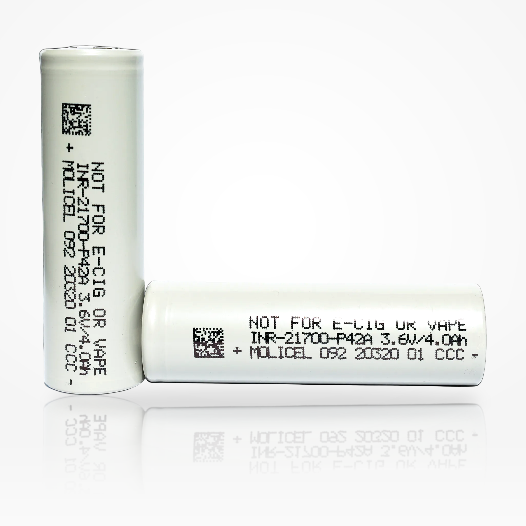
Molicel P42A 21700
Molicel P42A 21700
4200mAh / 45A
High-power 4.2Ah 21700 lithium-ion cell engineered for demanding applications that require high current capability, strong voltage support, and higher energy per cell than typical 18650 formats.
45A Continuous Discharge 4200mAh Typical Capacity 15.5Wh Typical Energy 3.6V Nominal Voltage 21700 Power Cell Unprotected Flat Top
45AContinuous Discharge
4200mAhTypical Capacity
4000mAhMinimum Capacity
10mΩAC Impedance @ 1kHz
4.2AStandard Charge Current
21.7 × 70.2mmMax Cell Envelope
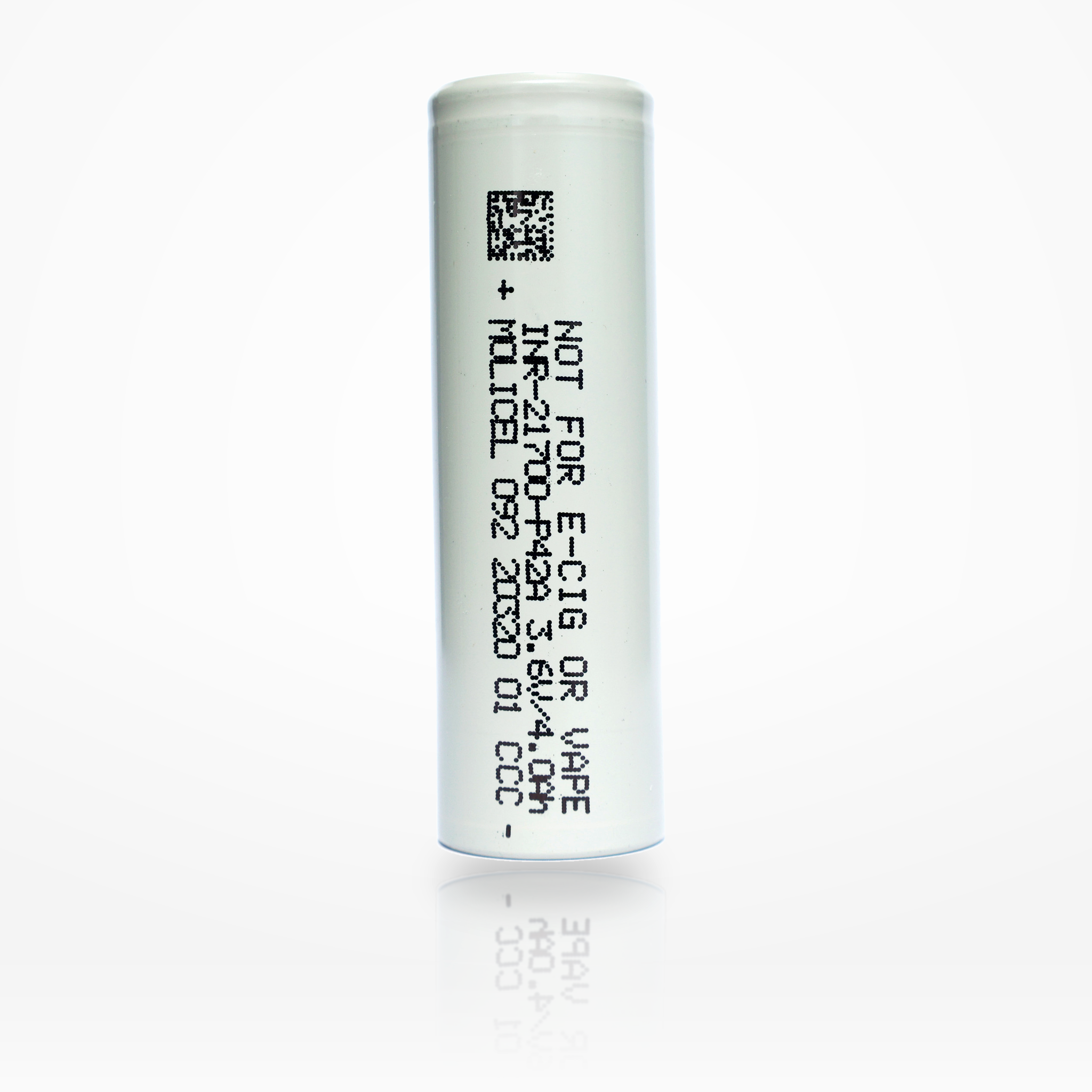
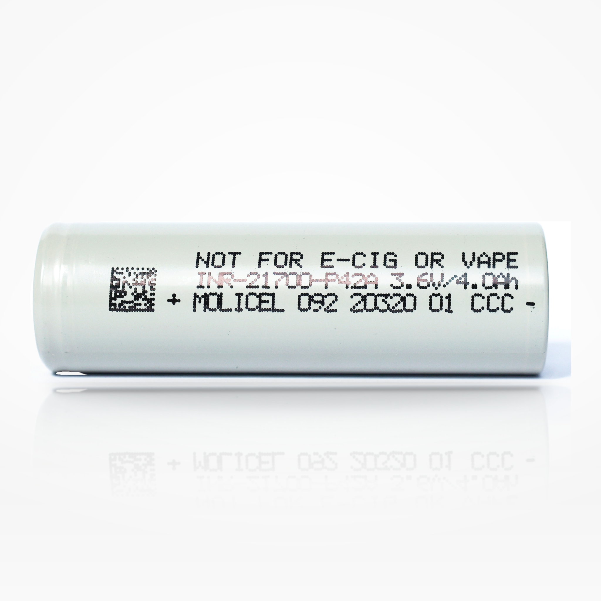
Molicel 21700 P42A 4200mAh 45A Battery
The Molicel P42A is a high-performance 21700 power cell built for high-drain use cases where current delivery and usable energy must be balanced in a compact cylindrical format. Compared with lower-capacity high-output cells, the P42A offers a useful combination of 4.2Ah typical capacity and 45A continuous discharge capability.
In practical design terms, the P42A is best viewed as a power-focused 21700: it delivers more runtime than many pure high-drain cells, while still supporting demanding current draw when the pack is properly designed, cooled, and protected.
| Brand / Model | Molicel INR-21700-P42A |
|---|---|
| Cell Series | Molicel Power Cell |
| Cell Type | 21700 cylindrical lithium-ion rechargeable cell |
| Typical Capacity | 4200mAh / 15.5Wh |
| Minimum Capacity | 4000mAh / 14.7Wh |
| Nominal Voltage | 3.6V |
| Charge Voltage | 4.20V |
| Discharge Cut-Off Voltage | 2.50V |
| Standard Charge Current | 4.2A CC-CV to 4.2V, 50mA cut at 23°C |
| Standard Charge Time | 1.5 hours |
| Continuous Discharge Current | 45A |
| Typical Impedance | 10mΩ AC at 1kHz; 16mΩ DC at 10A / 1s |
| Charge Temperature | 0°C to 45°C |
| Discharge Temperature | -40°C to 60°C |
| Energy Density | 615Wh/L volumetric; 230Wh/kg gravimetric |
| Dimensions | 21.7mm max diameter × 70.2mm max height |
| Weight | 70g max |
| Protection | No — unprotected flat-top cell |
Electrical operating envelope at a glance.
These quick-reference visuals summarize the P42A’s current capability, voltage window, energy translation, and C-rate interpretation.
1. Current Capability Stack
Key current reference points for charging, data-sheet discharge curves, and continuous discharge rating.
2. Voltage Operating Window
Basic per-cell voltage limits used for charger, BMS, and pack design.
3. Capacity and Energy Translation
The data sheet lists 15.5Wh typical energy; nominal-voltage math gives a close planning estimate.
4. C-Rate Conversion
For a 4200mAh cell, 1C equals approximately 4.2A.
| 0.84A | ≈0.2C rated / low-rate reference |
|---|---|
| 4.2A | 1C standard charge and discharge reference |
| 10A | ≈2.4C cycle / discharge reference |
| 20A | ≈4.8C high-load reference |
| 30A | ≈7.1C data-sheet curve reference |
| 45A | ≈10.7C continuous discharge rating |
High-current output should be evaluated with voltage sag, heat rise, and pack resistance in mind.
The P42A’s data sheet includes discharge-rate curves at 0.84A, 4.2A, 10A, 20A, and 30A, while the cell is specified for 45A continuous discharge. This makes it a strong choice for high-drain battery packs, but real performance depends on temperature, cell state of charge, nickel/busbar sizing, weld quality, airflow, and BMS/current limits.
The simplified discharge-curve graph below visualizes voltage versus delivered capacity under light, medium, and high-current conditions. It is not a digitized manufacturer curve; it is a product-page visualization designed to show how increasing load increases voltage sag and shortens usable capacity under cutoff-limited conditions.
Discharge-rate references
| 0.84A | Low-rate reference curve in data sheet |
|---|---|
| 4.2A | 1C discharge-temperature test current |
| 10A / 20A | Cycle-characteristics test currents |
| 30A | High-rate curve shown in data sheet |
| 45A | Specified continuous discharge current |
| Design takeaway | For high-current packs, validate voltage sag and cell temperature under the actual enclosure and cooling conditions. |
5. Simplified Discharge-Curve Graph
Voltage vs. capacity illustration for 4.2A, 20A, 30A, and 45A operation. Simplified for product-page visualization.
6. Estimated IR Voltage Drop
Planning reference using Molicel’s typical AC and DC impedance values. Real pack sag includes cells plus interconnects.
Charge, discharge, and thermal behavior should be treated as one system.
Molicel’s data sheet includes charge curves, discharge-rate curves, discharge-temperature curves, and cycle-characteristics curves. These visuals are condensed into customer-friendly diagrams below.
7. Charge Profile Reference
Standard charge: CC-CV to 4.2V with 50mA cut at 23°C. Data sheet also charts 8.4A charge behavior.
8. Thermal Operating Envelope
Published charge and discharge temperature ranges.
9. Discharge Rate Characterization
Customer-friendly summary of the data-sheet discharge-rate curve families.
10. Discharge Temperature Characterization
The data sheet charts 4.2A discharge behavior from -40°C through 60°C.
11. Cycle-Life Visualization
Data-sheet cycle characteristics are shown for 10A and 20A discharge to 2.5V at 23°C.
12. Energy Density Summary
Data-sheet energy density values for design comparison.
| Typical Energy | 15.5Wh |
|---|---|
| Minimum Energy | 14.7Wh |
| Volumetric Energy Density | 615Wh/L |
| Gravimetric Energy Density | 230Wh/kg |
| Design implication | Strong energy for a power cell, with significantly higher capacity than many high-drain 18650 options. |
21700 dimensional envelope for holders, sleds, weld fixtures, and pack CAD.
The product listing uses approximate dimensions, while Molicel’s data sheet provides the maximum envelope. Use the maximum values for fixture clearance, holder selection, and CAD checks.
13. Cell Dimension Diagram
Mechanical envelope based on Molicel maximum dimensions.
14. Pack Scaling Formulas
Quick math for series/parallel planning. Validate current limits thermally and electrically.
Pack Voltage ≈ Series Count × 3.6V
Pack Capacity ≈ Parallel Count × 4.2Ah
Pack Energy ≈ S × P × 15.5Wh
Cell-Level Current Capability ≈ Parallel Count × 45A
15. Example Parallel Scaling
Approximate scaling using cell-level continuous discharge rating, not a finished-pack guarantee.
| 1P | 4.2Ah, 15.5Wh, 45A cell-level current reference |
|---|---|
| 2P | 8.4Ah, 31.0Wh, 90A cell-level current reference |
| 3P | 12.6Ah, 46.5Wh, 135A cell-level current reference |
| 4P | 16.8Ah, 62.0Wh, 180A cell-level current reference |
| 5P | 21.0Ah, 77.5Wh, 225A cell-level current reference |
16. Common Series Voltage Examples
Nominal voltage examples only. Full-charge and cut-off pack voltages scale separately.
| 1S | 3.6V nominal / 4.2V full / 2.5V cut-off |
|---|---|
| 3S | 10.8V nominal / 12.6V full / 7.5V cut-off |
| 4S | 14.4V nominal / 16.8V full / 10.0V cut-off |
| 5S | 18.0V nominal / 21.0V full / 12.5V cut-off |
| 10S | 36.0V nominal / 42.0V full / 25.0V cut-off |
| 13S | 46.8V nominal / 54.6V full / 32.5V cut-off |
Use the P42A inside a controlled electrical and thermal system.
This is an unprotected high-power cell. Safe implementation requires a charger, BMS, fuse strategy, interconnect design, and thermal-management plan that respect the cell’s limits.
17. Suggested Control Threshold Map
System-level control guidance derived from the live listing and Molicel data-sheet values.
| Charge upper limit | 4.20V per cell |
|---|---|
| Discharge floor | 2.50V per cell |
| Charge temperature gate | 0°C to 45°C |
| Discharge temperature gate | -40°C to 60°C |
| Standard charge | 4.2A CC-CV to 4.2V, 50mA termination |
| Continuous current | 45A cell-level rating, subject to system-level thermal and interconnect validation |
18. Risk-Control Checklist
Recommended pack-building and use practices.
- Use only in devices or packs designed for lithium-ion 21700 cylindrical cells.
- Use a BMS or controller that monitors voltage, current, and temperature.
- Do not charge above 4.20V or discharge below 2.50V per cell.
- Validate high-current operation under the actual enclosure, cooling, and load profile.
- Never carry loose cells with conductive objects such as keys, coins, tools, or metal cases.
- Spot weld for pack assembly; do not solder directly to the cell body.
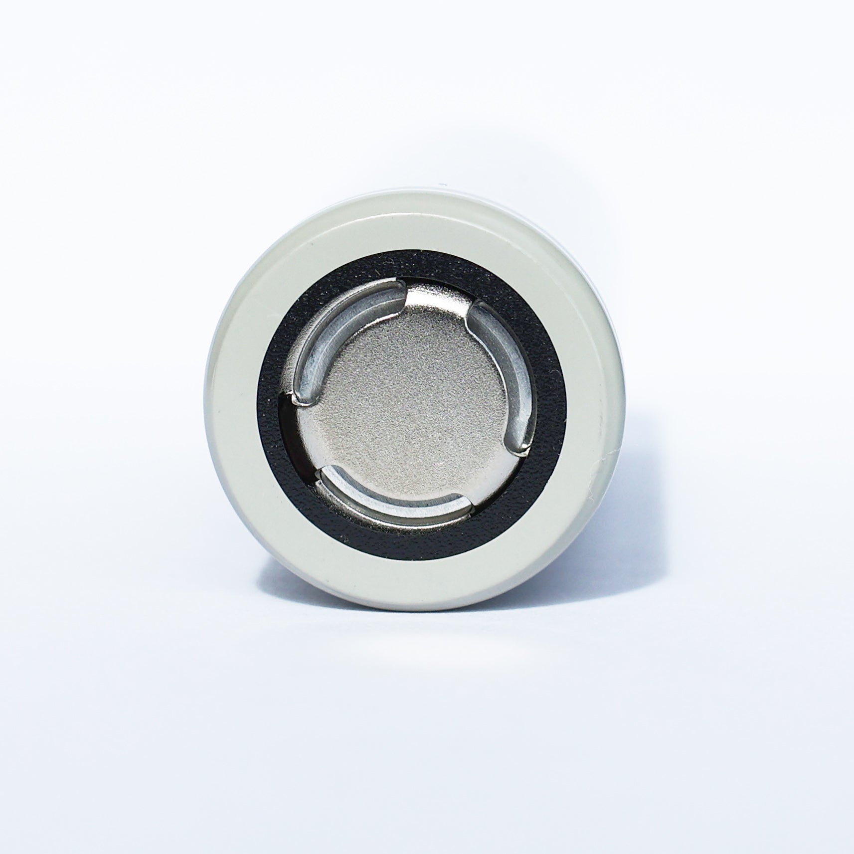
- Inspect wraps and top insulator rings before use.
- Size busbars, nickel, fuses, wiring, and BMS MOSFETs for both electrical resistance and heat rise.
Best suited for high-drain systems that need both power and capacity.
Power Tools
- Strong option for tool packs requiring high current per cell.
- Good balance of output and runtime in a compact 21700 footprint.
Drones / eVTOL
- Useful for high-power airborne systems where current density matters.
- Thermal validation is essential under peak discharge profiles.
E-Bike / Mobility
- Suitable for performance mobility packs when paired with correct BMS, fusing, and cooling.
- Parallel count should be based on measured current, voltage sag, and heat rise.
Robotics / RC
- Supports high motor current and compact pack geometry.
- Useful where power response and moderate energy density are both important.
High-Output Lighting
- Good fit for demanding LED systems that pull high current from each cell.
- Use only in devices designed for unprotected 21700 flat-top cells.
Custom Battery Packs
- Designed for experienced builders and integrators who can manage current sharing and heat.
- Requires matched cells, correct welding, insulation, protection electronics, and pack-level testing.
19. Selection Bias: Power vs. Runtime
for shoppers comparing high-power and high-energy cells.
20. Application Suitability Matrix
Simple product-page fit guidance.
| Power tools | Strong fit |
|---|---|
| Drones / eVTOL / RC | Strong fit |
| Performance mobility packs | Strong fit with validation |
| Runtime-focused electronics | Good, but may be more power than needed |
| Maximum runtime per cell | Consider higher-capacity energy cells |
| Unmanaged consumer devices | Not recommended |
Safety, Handling & Compatibility Notice
This product is an unprotected lithium-ion cell. It should only be used by customers who understand lithium-ion cell safety and who are using the battery in compatible hardware, managed packs, or professionally designed assemblies. Improper use can lead to overheating, venting, fire, or explosion.
- Charge only with lithium-ion chargers or managed battery systems designed for the correct chemistry and cell count.
- Never short circuit, crush, puncture, incinerate, or expose the cell to water.
- Do not use cells with damaged wraps, dented cans, or missing top insulator rings.
- Do not mix with cells of different age, capacity, model, or state of charge in the same pack.
- For assembly, use spot welding rather than direct soldering to reduce heat damage risk.
- Store and transport in non-conductive cases; never carry loose cells in pockets or bags.
- Keep away from children and from applications for which the product is not specified.
- Not for e-cigarette, vape, or similar use.
Common technical questions about the Molicel P42A.
What is the capacity of the Molicel P42A?
The P42A has a typical capacity of 4200mAh and a minimum capacity of 4000mAh. The data sheet lists typical energy as 15.5Wh and minimum energy as 14.7Wh.
What is the discharge rating?
The P42A is specified for 45A continuous discharge. Finished pack current should still be limited by thermal design, busbar/weld resistance, BMS ratings, fusing, and device requirements.
Is this a protected battery?
No. This is an unprotected flat-top 21700 cell and should be used only in equipment or packs with appropriate electrical and thermal protection.
What charger should be used?
Use a lithium-ion charger or battery-management system that uses a CC-CV profile to 4.20V per cell. The standard charge current listed by Molicel is 4.2A with 50mA termination at 23°C.
Can the P42A fast charge?
The product data sheet shows charge-characteristic curves at both 4.2A and 8.4A, while the published standard charge current is 4.2A. For applications using higher charge currents, validate temperature, cycle life, and manufacturer guidance for the complete system.
What is the correct discharge cut-off voltage?
The data sheet states a 2.50V discharge cut-off voltage per cell. Many pack designers choose a higher system cut-off to reduce stress and improve service life.
Can the P42A be used in battery packs?
Yes. It is a strong candidate for high-power custom battery packs when cell matching, spot welding, BMS sizing, fusing, insulation, and thermal validation are properly engineered.
Can I solder wires directly to this cell?
Direct soldering is not recommended. Spot welding is the preferred pack-assembly method because it reduces the risk of heat damage to the cell.
What are the cell dimensions?
Molicel lists the maximum cell envelope as 21.7mm diameter and 70.2mm height, with a maximum weight of 70g. Always confirm physical fit in the actual device or holder.
What temperature range is allowed?
The P42A data sheet lists 0°C to 45°C for charging and -40°C to 60°C for discharging. High-current use should include temperature monitoring and derating.
Is the P42A better for power or runtime?
It is primarily a power cell, but with a strong 4200mAh typical capacity. It is a good choice when both high current and useful runtime are needed in a 21700 format.
What does 10mΩ AC impedance mean?
It indicates low cell impedance, which helps support higher current delivery and reduced voltage sag. Real pack resistance also includes welds, nickel, busbars, wiring, holders, fuses, and BMS components.
How many cycles should I expect?
The product listing uses a general 300+ cycle-life description, while the data sheet shows cycle-characteristics curves at 10A and 20A discharge. Actual cycle life depends on temperature, charge voltage, discharge current, depth of discharge, and pack design.
Can I carry this battery loose?
No. Loose transport is unsafe because conductive objects can short the terminals. Always use a non-conductive battery case.
Customer Reviews
Overall rating: 4.9 / 5 from 1125 reviews.
Love the molicel 21700 batts, they last a good days worth of use on a single charge.

I have now received my parcel.
Great prices and fast shipping
5 stars plus. Will buy from again thanks
Best price. Quick delivery. Very happy!
It is the best

Molicell doesn't disappoint when I'm rebuilding failed Samsung packed power tool batteriesm
😊
My order was complete. Shipping was fast. Happy with my order. I will definitely use this company again. Satisfied with my purchase
Batteries arrived on time, are exactly what I needed! Thanks.

Muy buenas la recomendó
Shipping was fast. I always buy/trust 18650BatteryStore.com. Thank you!!!
Each battery came at 3.6v, packed nicely and shipped on time.
Amazing servicr
Great prices on the Molicel 21700 p42a cells!! Fast delivery too!! Will definitely be shopping here again!
Excellent product, fast shipping, and a trustworthy website. There is a reason so many flashlight enthusiasts recommend this site for batteries. Amazon and other sites unfortunately sometimes unknowingly sell counterfeit rewrapped batteries so I'm grateful this place exists for peace of mind!
Great batteries. Hold up well, great for higher draw flaslights, etc.
Good
Perfecto
Wanted p50b but was out of stock. Really wish yall would get the Epoch 21700 back in stock. Don’t look like that’s ever gonna happen.
Fast shipping
Great internal resistance all of them are within .1 milliohm.

Quick shipping, smooth process. I would recommend buying from this company & will do so again.
Been using this lithium battery for over 8 yrs. I use 2 of these per day every day. They each get recharged every day 365 days a yr. They aren't 100% depleted but are about 60 to 70% depleted when it charge them. They last for years and years and have only worn out 3 or 4 over the last 8 yrs. I do keep spares on hand just in case. I use these in high end flash lights, my Vape device, rechargeable fan that runs almost 24/7. You can't go wrong with this battery I've proofed that.
First time using these cells, so I don't know about long term, but are working very well out of the gate. Mainly for short-term, high-energy demand, 20 Volt Max power tools.
A+
good battery good packaging good price. love it
10/10 supplier
Great customer experience!
Long battery life.
This, Molicel 21700 IS THE BEST!
I’ve been purchasing batteries from 18650 Batteries for years now, both the titular 18650’s and now 21700’s. I definitely do not use them for vaping, and definitely haven’t been using them for vaping for the better part of a decade now. They’re always solid, and the best source for not vaping batteries around.
Thank you for the batteries, I'm using these with my new SKYRC MC5000 charger, and they are charging great. Using these with my EMISAR flashlights. 21700 is the perfect battery size.
You guys are great as is your customer service. It is rare this day and age when you can talk to a knowledgeable person on the phone. Keep up the good work! On the other hand I had two batteries out of my order that would not fully charge. What can be done?
works perfectly
EXCELENTE!!!
To be honest, I thought that order was 18650's. Had to go look at the invoice, but there it was, 21700's. It all worked out because I just got some Makita battery kits that took 21700's. This company is so darn good they sent me what I needed, not what I wanted.
Great price and quality for battery pack building!
Made a mistake, needed a higher discharge rate so these don't really help with what I needed them for