
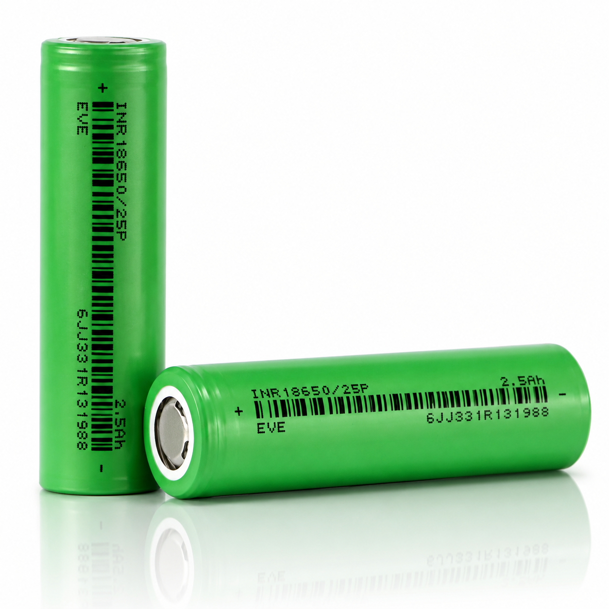


EVE 25P 18650
2500mAh / 20A
High-drain 2.5Ah 18650 lithium-ion cell designed for compact battery packs, lighting, tools, RC systems, and other applications that need stable current delivery in the widely used 18650 format.
EVE 25P 18650 2500mAh 20A Battery
The EVE 25P is a power-oriented 18650 cell for applications that need more current than a typical energy cell while retaining usable 2500mAh-class runtime. It is especially useful in cost-sensitive pack builds, flashlights, compact power tools, RC systems, robotics, and other moderate-to-high drain applications.
| Brand / Model | EVE / INR18650-25P |
|---|---|
| Cell Type | 18650 cylindrical lithium-ion rechargeable cell |
| Nominal Capacity | 2500mAh |
| Standard Discharge Capacity | ≥2450mAh under IEC61960 reference method |
| Nominal Voltage | 3.60V |
| Charge Voltage | 4.20V ±0.05V |
| Discharge Cut-Off Voltage | 2.50V per cell |
| Standard Charge | CC-CV, 1.25A, 4.20V, 100mA cut-off |
| Rapid Charge | CC-CV, 4A, 4.20V, 100mA cut-off |
| Standard Discharge | 0.5A to 2.50V cut-off |
| Live Listing Rating | 20A continuous discharge rating |
| Datasheet Max Continuous | 30A maximum continuous discharge to 2.50V cut-off |
| Initial Internal Impedance | ≤18mΩ AC at 1kHz at shipping state of charge |
| Dimensions | 65.00 ±0.15mm height; 18.35 ±0.10mm diameter, with tube |
| Weight | 48.0g maximum; live listing states approximately 45g |
| Ambient Temperature | Charge: 0°C to 45°C; Discharge: -20°C to 60°C |
| Cell-Surface Cut-Off Temperature | Charge: 0°C to 50°C; Discharge: -20°C to 80°C; recommended re-discharge release <60°C |
| Storage | At shipping SOC: 1 year at 0°C to 25°C; 3 months at 0°C to 45°C; 1 month at 0°C to 60°C |
| Protection | No — unprotected bare cell |
Electrical operating envelope at a glance.
These quick-reference visuals summarize the EVE 25P’s current layers, voltage limits, capacity-to-energy translation, and C-rate conversion.
1. Current Capability Stack
Customer-facing 20A listing rating plus EVE’s 30A maximum continuous specification.
2. Voltage Operating Window
Basic per-cell voltage limits used for charger, BMS, and pack configuration.
3. Capacity and Energy Translation
Nominal watt-hours are calculated from nominal capacity and nominal voltage.
4. C-Rate Conversion
For a 2500mAh cell, 1C equals approximately 2.5A.
| 0.5A | 0.2C standard discharge reference |
|---|---|
| 1.25A | 0.5C standard charge |
| 4A | 1.6C rapid charge |
| 10A | 4C high-drain reference |
| 20A | 8C live listing continuous discharge rating |
| 30A | 12C data-sheet maximum continuous discharge condition |
Rate capability: strong power-cell behavior in a compact 18650 package.
The EVE specification compares relative capacity at 0.5A, 2.5A, 10A, 15A, and 20A after standard charge. Relative capacity remains at or above 95% for the published table entries, with 10A used as the reference comparison value. This supports the cell’s high-drain positioning while still keeping the live listing at a conservative 20A CDR.
The simplified discharge graph below shows voltage versus capacity under 0.5A, 10A, 20A, and 30A loading. Heavier discharge curves are drawn lower to communicate the effect of voltage sag and thermal load at higher current.
Relative rate capability summary
| 0.5A | ≥100% relative capacity |
|---|---|
| 2.5A | ≥95% relative capacity |
| 10A | 100% reference capacity |
| 15A | ≥95% relative capacity |
| 20A | ≥95% relative capacity |
| Interpretation | Published data supports stable capacity delivery at moderate-to-high discharge currents, but high-current pack use still requires thermal validation. |
5. Simplified Discharge-Curve Graph
Voltage vs. capacity illustration under 0.5A, 10A, 20A, and 30A constant-current discharge. Simplified for product-page visualization.
6. Estimated IR Voltage Drop
Using the published ≤18mΩ AC impedance as a rough planning reference. Real DC sag varies with SOC, temperature, age, and pack resistance.
Thermal conditions strongly affect charge acceptance, discharge performance, and cycle life.
EVE’s specification includes charge/discharge temperature boundaries, relative capacity at several temperatures, and a cycle-life criterion under rapid-charge and 20A discharge conditions.
7. Charge Profile Reference
Standard charge: 1.25A CC-CV to 4.20V with 100mA termination. Rapid charge: 4A CC-CV to 4.20V with 100mA termination.
8. Thermal Operating Envelope
Ambient and cell-surface operating guidance from the product specification.
9. Temperature Discharge Capacity
Relative capacity at 10A discharge after 3 hours storage at the test temperature, normalized to 25°C.
10. Cycle-Life Visualization
Published criterion: ≥1500mAh after 300 cycles using rapid charge and 20A discharge to 80°C / 2.50V cut-off.
18650 dimensional envelope for holders, sleds, weld fixtures, and pack CAD.
Mechanical fit is especially important in dense assemblies. The EVE specification provides with-tube dimensions of 65.00±0.15mm height and 18.35±0.10mm diameter.
11. Cell Dimension Diagram
Mechanical envelope based on the published specification dimensions.
12. Pack Scaling Formulas
Quick math for designers building series/parallel battery packs.
Pack Voltage ≈ Series Count × 3.6V
Pack Capacity ≈ Parallel Count × 2.5Ah
Pack Energy ≈ S × P × 9.0Wh
Listing Current ≈ Parallel Count × 20A
13. Example Parallel Scaling
Approximate scaling, assuming balanced cells and proper thermal/electrical design.
| 1P | 2.5Ah, 9.0Wh, 20A listing rating / 30A spec max |
|---|---|
| 2P | 5.0Ah, 18.0Wh, 40A listing rating / 60A spec max |
| 3P | 7.5Ah, 27.0Wh, 60A listing rating / 90A spec max |
| 4P | 10.0Ah, 36.0Wh, 80A listing rating / 120A spec max |
14. Common Series Voltage Examples
Nominal voltage examples only. Full-charge and cut-off pack voltages scale separately.
| 1S | 3.6V nominal / 4.2V full / 2.5V cut-off |
|---|---|
| 3S | 10.8V nominal / 12.6V full / 7.5V cut-off |
| 4S | 14.4V nominal / 16.8V full / 10.0V cut-off |
| 5S | 18.0V nominal / 21.0V full / 12.5V cut-off |
| 10S | 36.0V nominal / 42.0V full / 25.0V cut-off |
Use the EVE 25P inside a controlled electrical and thermal system.
This is an unprotected lithium-ion cell. Safe implementation requires charge, discharge, short-circuit, over-temperature, and under-voltage protection.
15. Suggested Control Threshold Map
System-level control guidance derived from the published operating range.
| Charge upper limit | 4.20V ±0.05V per cell |
|---|---|
| Discharge floor | 2.50V per cell |
| Standard charge current | 1.25A CC-CV to 100mA cut-off |
| Rapid charge current | 4A CC-CV to 100mA cut-off |
| Customer-facing current | 20A CDR listing value |
| Engineering validation zone | 30A maximum continuous data-sheet condition |
16. Risk-Control Checklist
Recommended pack-building and use practices.
- Use only in devices or packs designed for lithium-ion 18650 cells.
- Do not charge above 4.20V or discharge below 2.50V per cell.
- Use a charger/BMS that monitors voltage, current, and temperature.
- Never carry loose cells with conductive objects such as keys or coins.
- Spot weld for pack assembly; do not solder directly to the cell body.
- Inspect wraps and insulator rings before use; rewrap or recycle damaged cells.
Best suited for compact high-drain systems where value and current delivery matter.
Power Tools
- Good choice for compact drill, driver, and tool packs.
- Use appropriate BMS and heat management under sustained load.
RC / Robotics
- Useful in motor-driven systems that need high current from 18650 cells.
- Validate voltage sag at the actual duty cycle.
High-Output Lighting
- Suitable for compatible lights that need more current than energy cells provide.
- Confirm device compatibility with unprotected flat-top cells.
Custom Packs
- Works well in cost-sensitive packs where 2.5Ah capacity and high current are balanced.
- Requires matched cells, good welds, insulation, and BMS protection.
E-Bike / Mobility Modules
- Can be used where pack count and thermal design support the current draw.
- Do not exceed pack-level thermal and BMS limits.
General Electronics
- Use only when the device can safely manage an unprotected high-current cell.
- For low-load runtime applications, a higher-capacity energy cell may be better.
Safety, Handling & Compatibility Notice
This product is an unprotected lithium-ion cell. It should only be used by customers who understand lithium-ion safety and who are using the battery in compatible hardware, managed packs, or professionally designed assemblies. Improper use can lead to overheating, venting, fire, or explosion.
- Charge only with lithium-ion chargers or managed battery systems designed for the correct chemistry and cell count.
- Never short circuit, crush, puncture, incinerate, or expose the cell to water.
- Do not use cells with damaged wraps, dented cans, or missing top insulator rings.
- Do not mix with cells of different age, capacity, model, or state of charge in the same pack.
- For assembly, use spot welding rather than direct soldering to reduce heat damage risk.
- Store and transport in non-conductive cases; never carry loose cells in pockets or bags.
- Not for e-cigarette, vape, or similar use.
Common technical questions about the EVE 25P.
What is the capacity of the EVE 25P?
The nominal capacity is 2500mAh. EVE’s specification also lists a standard discharge capacity criterion of at least 2450mAh under its reference test method.
Is this a 20A or 30A battery?
The live product listing describes it as a 20A battery. The EVE specification lists 30A maximum continuous discharge to 2.50V. Use 20A for conservative product-page CDR language and treat 30A as an engineering maximum that requires thermal validation.
Is this cell protected?
No. This is an unprotected bare cell and should be used only in devices or packs with suitable protection electronics.
What charger should be used?
Use a lithium-ion CC-CV charger that charges to 4.20V per cell. The standard charge current is 1.25A and the rapid charge current is 4A.
What is the discharge cut-off voltage?
The specification states a 2.50V discharge cut-off voltage per cell.
Can the EVE 25P be used in battery packs?
Yes. It is suitable for custom packs when cells are matched and the pack includes correct welding, insulation, fusing, BMS protection, and thermal validation.
Can I solder wires directly to this cell?
Direct soldering is not recommended. Spot welding is preferred for pack assembly because it reduces heat damage risk.
What are the cell dimensions?
The EVE specification lists 65.00 ±0.15mm height and 18.35 ±0.10mm diameter, with tube.
What temperature range is allowed?
The specification lists ambient charge from 0°C to 45°C and ambient discharge from -20°C to 60°C. Cell-surface cut-off limits extend to 50°C for charge and 80°C for discharge, with release thresholds specified.
How many cycles should I expect?
The specification gives a cycle-life criterion of at least 1500mAh after 300 cycles under rapid-charge and 20A discharge conditions. Real service life depends on current, temperature, depth of discharge, charge voltage, and pack design.
What does ≤18mΩ internal resistance mean?
It indicates relatively low impedance, which supports higher current delivery and reduced voltage sag. Real pack resistance also includes welds, nickel, busbars, holders, wiring, and the BMS.
Can I carry this battery loose?
No. Loose transport is unsafe because metal objects can short the terminals. Always use a non-conductive battery case.
Technical product-page content based on the current 18650BatteryStore product listing and EVE INR18650/25P specification. Verify all values against the latest manufacturer documentation and complete pack-level testing before production use.