
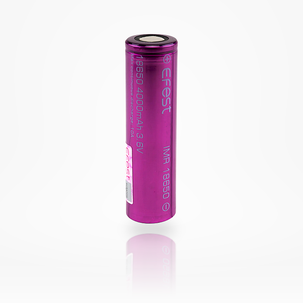


Efest 18650
4000mAh / 10A IMR
A high-capacity Efest-labeled 18650 lithium-ion cell intended for low-to-moderate drain applications, extended runtime, and protected pack/device use. Because Efest is a rewrap brand, published ratings should be treated as label/listing claims and bench verified before pack integration.
Efest 18650 4000mAh 10A IMR Battery
The Efest 18650 4000mAh 10A IMR Battery is positioned as a runtime-focused 18650 for low-to-moderate drain devices. The listing highlights a 4000mAh capacity, 3.7V nominal voltage, 4.20V full-charge voltage, 2.50V discharge cut-off, 10A continuous discharge rating, unprotected construction, and approximately 300+ charge cycles.
Because this is a rewrap-brand product, the safest professional copy should not imply that the underlying OEM cell is known, traceable, or independently validated by the label alone. For pack use, every incoming batch should be tested for capacity, resistance, temperature rise, voltage sag, and lot consistency before it is committed to a production or high-risk pack.
Rewrap-brand bench-verification notice
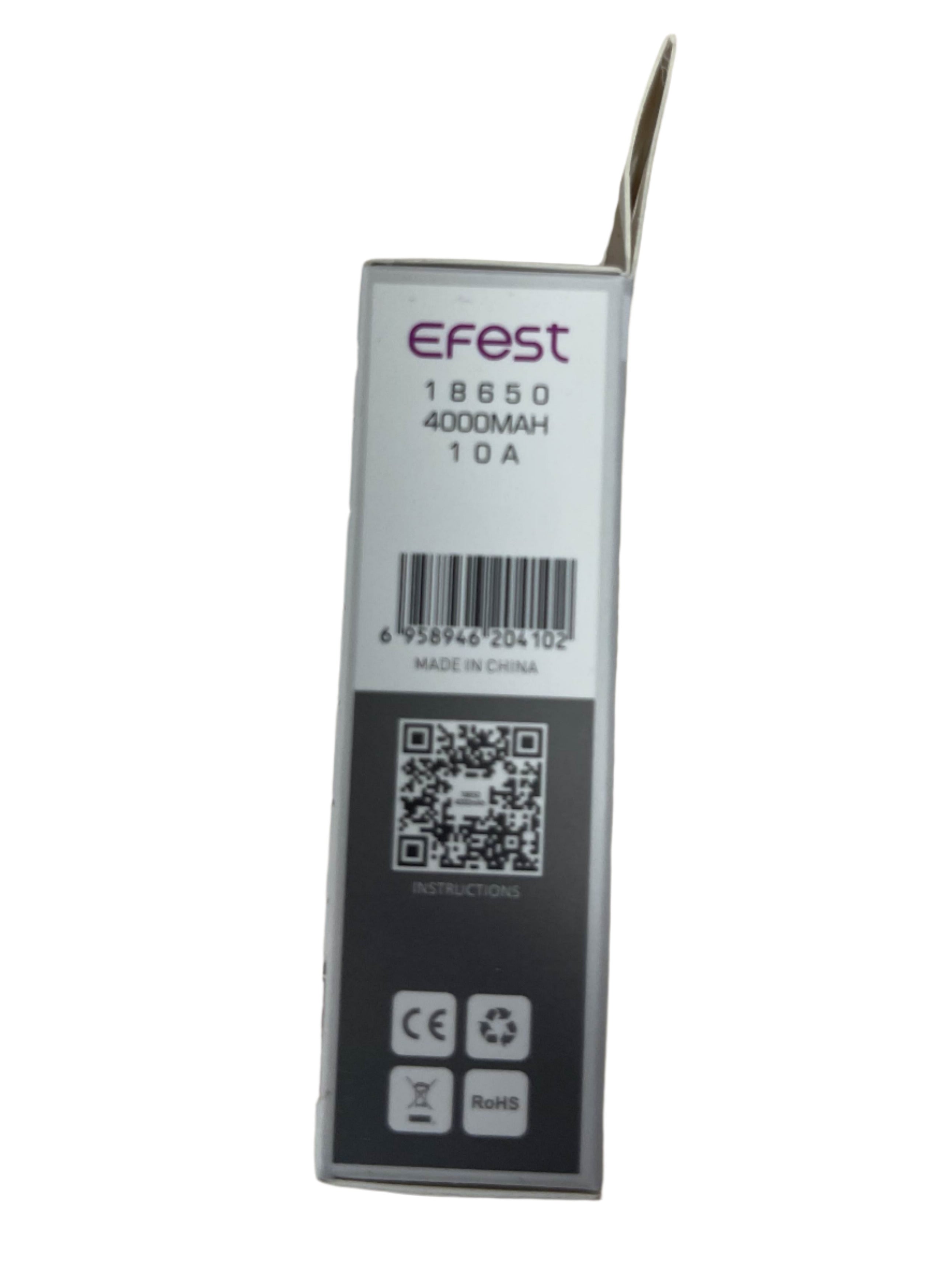
Efest is a rewrap brand. Do not assume the wrap label alone proves the original cell manufacturer, exact chemistry, internal construction, or sustained pack-level current capability. Treat the 4000mAh / 10A listing as a commercial rating that must be verified under your real charger, BMS, holder, weld, enclosure, and load conditions before pack deployment.
| Specification | Listing / Technical Copy Value |
|---|---|
| Brand / Product | Efest 18650 4000mAh 10A IMR Battery |
| Brand Type | Rewrap label; bench verification recommended before pack use |
| Battery Size | 18650 cylindrical lithium-ion cell |
| Capacity | 4000mAh listing capacity |
| Nominal Voltage | 3.7V |
| Full Charge Voltage | 4.20V |
| Discharge Cut-Off | 2.50V |
| Continuous Discharge Rate | 10A listing CDR |
| Estimated Nominal Energy | Approx. 14.8Wh using 4.0Ah × 3.7V |
| Cycle-Life Expectation | Listing states approximately 300+ charge cycles |
| Dimensions | Approx. 18.3mm diameter × 65.0mm length |
| Weight | Approx. 48g |
| Protection | Unprotected cell — external protection required |
| Best-Fit Applications | Low-to-moderate drain devices, flashlights, power banks, low-drain packs, and consumer electronics where verified current draw stays within limits |
Voltage, current, capacity, and C-rate visualization.
These visuals explain the listing specifications in an engineering-friendly format. Since this is a rewrap-brand cell, use the charts as product-page illustrations only; pack builders should verify actual cell behavior with bench tests.
1. Current Capability Stack
Listing current rating shown against lower operating-current examples.
2. Voltage Operating Window
Basic per-cell voltage limits for charge and discharge control.
3. Capacity and Energy Translation
Capacity is stated in amp-hours; energy depends on nominal voltage.
4. C-Rate Conversion
For a 4000mAh listing capacity, 1C equals approximately 4A.
| 1C | ≈4A |
|---|---|
| 0.5C | ≈2A gentle-to-moderate charge/discharge reference |
| 3A | ≈0.75C light-to-moderate discharge |
| 6A | ≈1.5C moderate discharge |
| 10A | ≈2.5C listing continuous-discharge rating |
Simplified discharge behavior and bench-test warning.
Without an original OEM data sheet linked to the product page, discharge curves should be presented as schematic illustrations rather than guaranteed performance curves. The graph below shows the expected pattern: higher current creates more voltage sag and shorter runtime, while lower current preserves a flatter voltage profile and more usable capacity.
Pack-build recommendation: test a representative sample from each lot at the intended current profile, with cell-surface temperature logging, before committing this rewrap-labeled cell to a pack.
Bench verification targets
| Capacity check | Measure delivered mAh at a defined current and cut-off voltage |
|---|---|
| IR / DCIR | Measure resistance and compare cell-to-cell spread |
| Thermal profile | Log cell surface temperature at intended load |
| Voltage sag | Confirm device or BMS will not trip early under load |
| Lot consistency | Verify cells in the same pack are matched closely |
5. Simplified Discharge-Curve Graph
Voltage vs. capacity illustration for light, moderate, and 10A listing-current use. Schematic only; bench verify real cells.
6. Idealized Runtime by Current
Simple theoretical estimate from 4.0Ah capacity. Real runtime depends on cut-off, sag, temperature, and actual measured capacity.
Bench verification should happen before this cell is placed into a pack.
For a rewrap-brand cell, the most professional product description should actively explain that label claims are not a substitute for incoming quality control. The workflow below is written for pack builders, resellers, and technical buyers.
7. Rewrap Risk-Control Matrix
What must be confirmed before a rewrap-branded cell goes into a pack.
| Claim | 4000mAh capacity | Bench capacity test |
|---|---|---|
| Claim | 10A CDR | Thermal load test |
| Claim | IMR label | Do not infer OEM chemistry |
| Claim | 300+ cycles | Cycle validation if critical |
| Claim | Pack suitability | Pack-level BMS required |
8. Stress Map by Current
Qualitative current-stress guide for low-to-moderate drain applications.
18650 dimensional envelope and basic pack scaling.
9. Cell Dimension Diagram
Listing dimensions are approximate; measure real samples before designing tight holders.
10. Pack Scaling Formulas
Use these formulas for early planning only. Pack ratings must be verified.
Pack Voltage ≈ Series Count × 3.7V
Pack Capacity ≈ Parallel Count × 4.0Ah
Pack Energy ≈ S × P × 14.8Wh
Listing Current ≈ Parallel Count × 10A
11. Example Parallel Scaling
Approximate scaling using listing capacity and listing CDR.
| 1P | 4.0Ah, 14.8Wh, 10A listing CDR |
|---|---|
| 2P | 8.0Ah, 29.6Wh, 20A listing CDR |
| 3P | 12.0Ah, 44.4Wh, 30A listing CDR |
| 4P | 16.0Ah, 59.2Wh, 40A listing CDR |
| 5P | 20.0Ah, 74.0Wh, 50A listing CDR |
12. Common Series Voltage Examples
Nominal voltage examples only; full-charge and cut-off values scale separately.
| 1S | 3.7V nominal / 4.2V full / 2.5V cut-off |
|---|---|
| 2S | 7.4V nominal / 8.4V full / 5.0V cut-off |
| 3S | 11.1V nominal / 12.6V full / 7.5V cut-off |
| 4S | 14.8V nominal / 16.8V full / 10.0V cut-off |
| 10S | 37.0V nominal / 42.0V full / 25.0V cut-off |
Use only inside a controlled lithium-ion electrical system.
This is an unprotected cell. For pack use, design and test around the actual measured behavior of the cells you received.
13. Suggested Control Threshold Map
Basic controls for a BMS or protected device.
| Charge upper limit | 4.20V per cell |
|---|---|
| Discharge floor | 2.50V per cell listing value; consider higher pack-level cut-off for life extension |
| Current limit | 10A listing CDR; validate heat rise before pack use |
| Thermal protection | Required for any pack that approaches the CDR repeatedly or continuously |
| Pack matching | Capacity, voltage, resistance, age, and lot should be matched before assembly |
14. Risk-Control Checklist
Recommended use practices for rewrap-labeled unprotected cells.
- Do not use in e-cigarettes, vaporizers, or similar devices.
- Use a proper lithium-ion smart charger or BMS.
- Never charge unattended or on combustible surfaces.
- Never carry loose in a pocket, purse, bag, or toolbox.
- Do not short circuit, puncture, crush, cut, modify, or incinerate.
- Do not solder directly to the cell; use spot welding for pack assembly.
- Do not mix old/new, used/unused, or mismatched cells.
- Bench test samples from every lot before putting them into a pack.
Best suited for runtime-focused, low-to-moderate drain applications.
Efficient LED Lighting
- Good fit where runtime is more important than extreme current.
- Verify physical flat-top compatibility.
Power Banks
- Useful in protected low-current portable power designs.
- Bench capacity test before production use.
Consumer Electronics
- Appropriate for low-to-moderate current devices.
- Use only with compatible lithium-ion protection.
Backup Modules
- Suitable for intermittent or low-drain backup packs.
- Cycle and storage behavior should be verified.
Custom Packs
- Can be used if cells are matched and validated.
- Not recommended for high-risk packs without incoming QC.
Not High-Drain First Choice
- Choose a known OEM high-drain cell for power tools, drones, or high-current packs.
- Do not exceed verified performance limits.
15. Selection Bias: Runtime vs. Power
How to position the Efest 4000mAh 10A cell.
16. Application Suitability Matrix
Simple product-page fit guidance.
| Runtime-focused lights | Good fit if compatible |
|---|---|
| Power banks | Good fit with protection |
| Low-drain electronics | Good fit |
| Battery packs | Bench verify first |
| Power tools / drones | Use known high-drain OEM cell |
Safety, Handling & Compatibility Notice
This product is an unprotected lithium-ion cell. It should only be used by customers who understand cell-level lithium-ion safety and who are using the battery in compatible hardware, protected devices, or professionally designed assemblies. Improper use can lead to overheating, venting, fire, or explosion.
- Only purchase and use if you understand lithium-ion battery safety.
- Charge in or on a fire-resistant surface and never leave cells charging unattended.
- Use only a compatible smart charger designed for lithium-ion cells.
- Store in a protective case; never carry loose in a pocket, bag, or purse.
- Keep away from metal objects to prevent short circuits.
- Use only within verified specifications and in protected devices or packs.
- Do not use in e-cigarettes, vaporizers, or similar devices.
- Do not short circuit, puncture, cut, crush, incinerate, modify, overcharge, or over-discharge.
- Do not solder directly; use spot welding for pack assembly.
Common technical questions about the Efest 18650 4000mAh 10A.
Is Efest a rewrap brand?
Yes. Efest is generally treated as a rewrap brand, meaning the wrap label does not itself identify the original OEM cell or guarantee unchanged sourcing over time. Bench verification is recommended before pack use.
What is the listed capacity?
The product listing states 4000mAh capacity. Because this is a rewrap-labeled product, pack builders should verify delivered capacity using their own test current, charger, cut-off voltage, and acceptance criteria.
What is the listed continuous discharge rating?
The listing states 10A continuous discharge. Before using this in a pack, verify voltage sag and cell-surface temperature at the intended current profile.
Is this a protected battery?
No. The listing identifies it as unprotected. Use only in devices or packs with appropriate voltage, current, short-circuit, and thermal protection.
What charger should be used?
Use a lithium-ion smart charger or BMS designed for 4.20V CC/CV charging. Do not use chargers intended for other chemistries.
What is the discharge cut-off voltage?
The product listing states a 2.50V discharge cut-off. Many pack designers use a higher practical cut-off to reduce stress and improve cycle life.
Can this cell be used in a battery pack?
It can be used only after incoming QC and bench validation. Test capacity, resistance, thermal rise, voltage sag, and cell-to-cell matching before assembly.
Can I solder directly to it?
No. Direct soldering can overheat the cell. Use proper spot welding and pack-building insulation practices.
What applications fit this cell best?
Low-to-moderate drain flashlights, portable electronics, power banks, and protected backup modules are better fits than high-current applications.
Is this appropriate for power tools or drones?
Not as a first-choice high-drain cell. For power tools, drones, and other high-current packs, use a known OEM high-drain cell with a manufacturer data sheet and validated pack design.
Can this be used in vape or e-cigarette devices?
No. The product page explicitly prohibits use in e-cigarettes, vaporizers, and similar devices.
How should I transport it?
Always use a non-conductive battery case. Never carry loose cells with keys, coins, tools, or other conductive objects.