
Looked everywhere for backup batteries for my pixel lightsabers. First brand I tried (not these) exploded for seemingly no reason. These work great. So far they seem to give me all the power these high drain pixel sabers need


product description
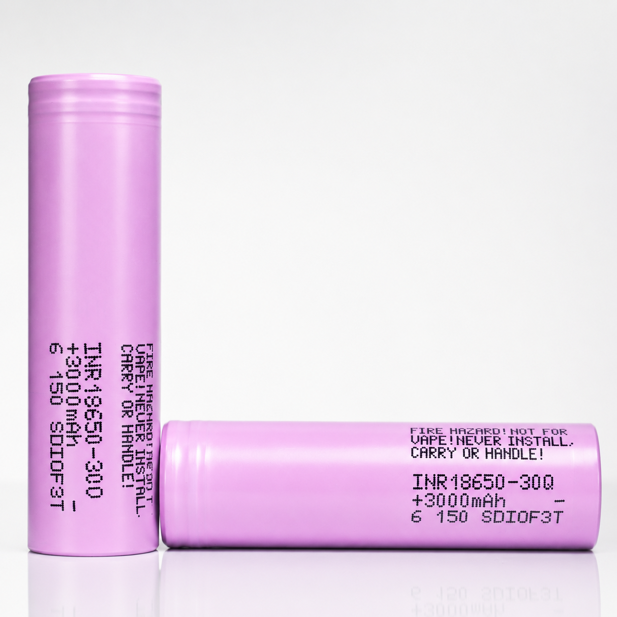
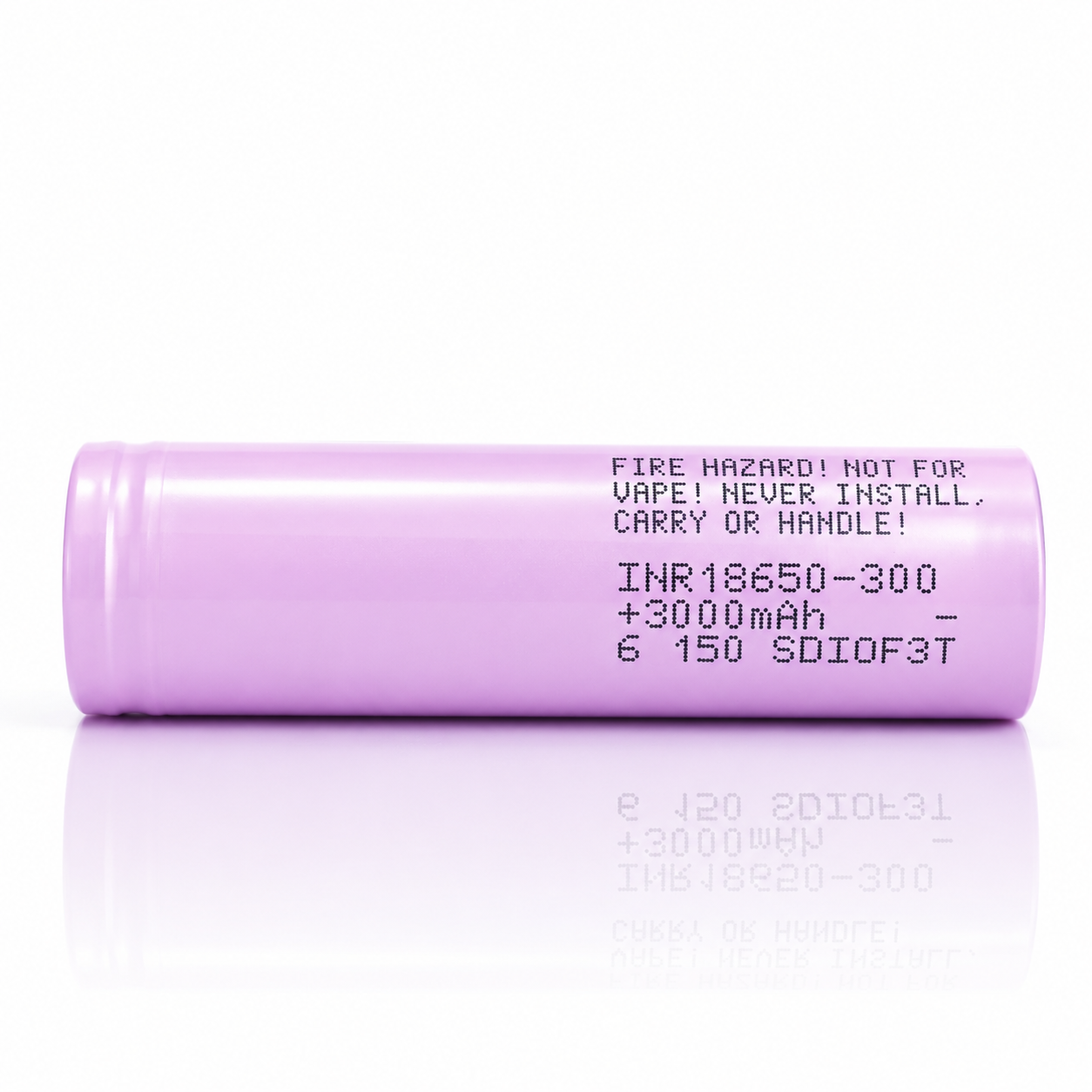
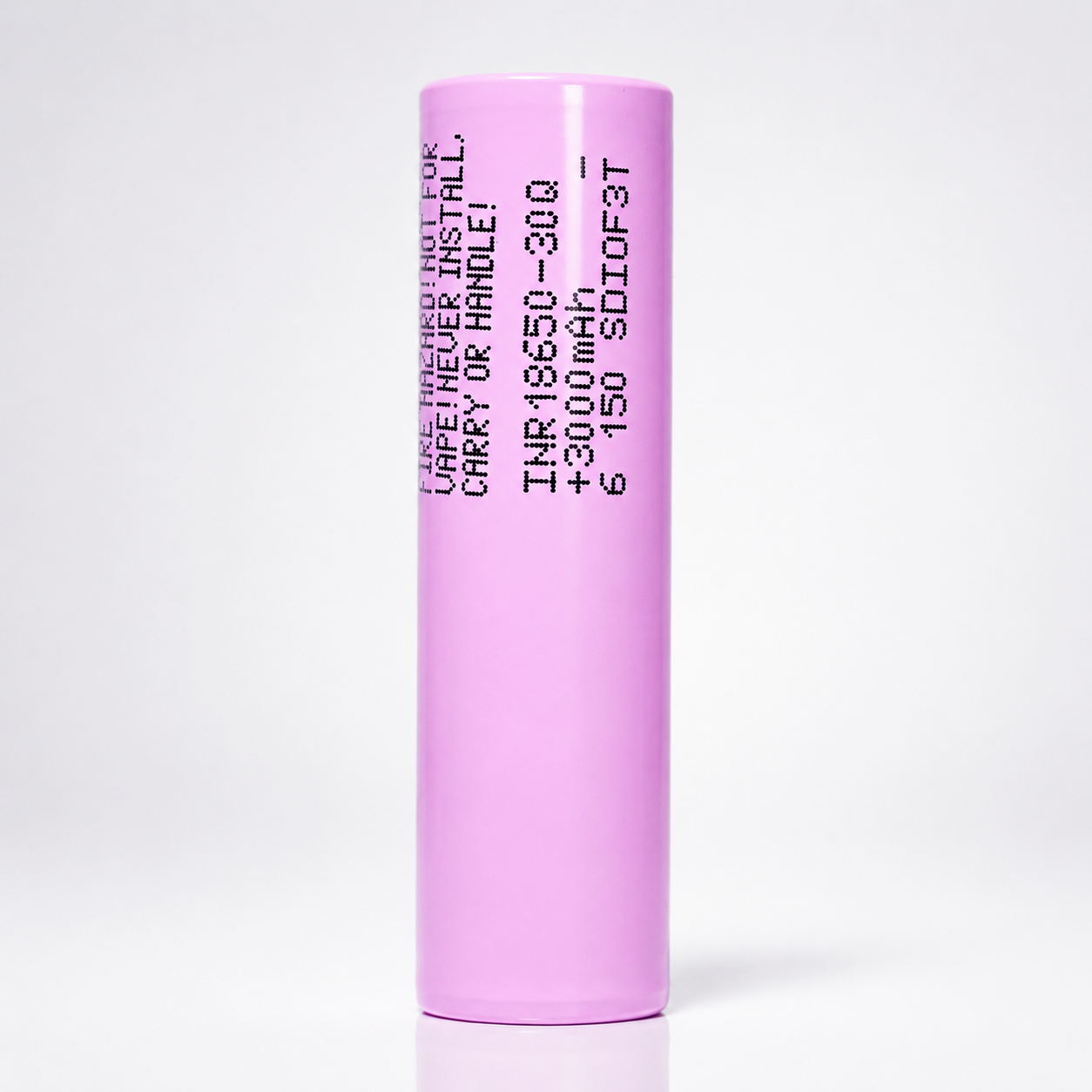
Samsung 30Q 18650
Samsung 30Q 18650
3000mAh / 15A
Balanced high-drain 3.0Ah 18650 lithium-ion cell designed for applications that need a practical mix of runtime, current capability, compact size, and pack-building flexibility. This Shopify-ready page summarizes the live product listing and Samsung SDI specification into a technical, chart-heavy layout for customers comparing voltage behavior, rate capability, cycle life, thermal limits, and fitment.
3000mAh Class Capacity 15A Continuous Discharge 4A Rated Charge 3.6V Nominal Voltage 18650 Form Factor Unprotected Flat Top
3000mAh class capacity
2950mAh minimum capacity
15AMax Continuous Discharge
4ARated Charge Current
≤26mΩInitial AC Impedance
18.4 × 65.0mmMax Cell Envelope
Samsung 30Q 18650 3000mAh 15A Battery
The Samsung INR18650-30Q sits in the balanced high-drain category. It offers more capacity than many ultra-power-focused 18650 cells while still providing a 15A continuous discharge rating. That makes it useful for flashlights, custom packs, moderate power tools, robotics, portable equipment, and other designs that require stable 18650 performance without moving to a lower-capacity cell.
In practical design terms, the 30Q is best viewed as a capacity-forward high-drain cell: strong 3.0Ah-class runtime with enough current support for medium-to-high drain devices. For engineering calculations, use 2950mAh minimum capacity, 2900mAh rated 10A discharge capacity, and 15A maximum continuous discharge at 25°C.
Design note: the simplified charts below are presentation-oriented engineering visuals built from the published specification and test conditions. They are meant for product-page comparison and pack-planning guidance, not as a substitute for full validation testing in the final application.
| Brand / Model | Samsung SDI INR18650-30Q |
|---|---|
| Cell Type | 18650 cylindrical lithium-ion rechargeable cell |
| Nominal / Advertised Capacity | 3000mAh class |
| Minimum Capacity | 2950mAh at 0.2C discharge to 2.5V |
| Rated Discharge Capacity | ≥2900mAh at 10A discharge to 2.5V after rated charge |
| Nominal Voltage | 3.6V |
| Charge Cut-Off Voltage | 4.20V ±0.05V |
| Discharge Cut-Off Voltage | 2.50V |
| Standard Charge Method | 1.50A CC-CV to 4.2V, terminate at 150mA |
| Rated Charge Method | 4A CC-CV to 4.2V, terminate at 100mA |
| Charging Time | Approx. 180 minutes standard charge; approx. 70 minutes rated charge at 25°C |
| Max Continuous Discharge | 15A at 25°C 60% at 250 cycle criterion |
| Initial Impedance | ≤26mΩ AC impedance at 1kHz after standard charge |
| Dimensions | 18.4mm max diameter × 65.0mm max height, with tube |
| Weight | 48.0g max |
| Charge Temperature | 0°C to 50°C Recommended recharge release <45°C |
| Discharge Temperature | -20°C to 75°C Recommended re-discharge release <60°C |
| Storage Temperature | 1.5 years: -30°C to 25°C; 3 months: -30°C to 45°C; 1 month: -30°C to 60°C, at ex-factory SOC |
| Shipment Voltage | 3.620V to 3.690V |
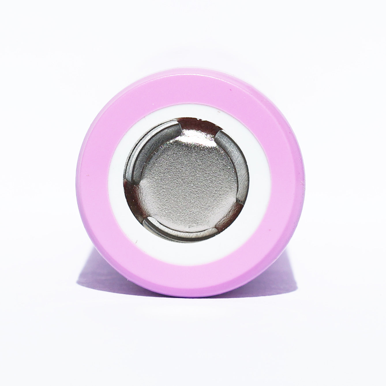
| Protection | No — unprotected bare cell |
Electrical operating envelope at a glance.
These quick-reference visuals summarize how the cell behaves in relation to current, voltage window, capacity-to-energy translation, and C-rate interpretation.
1. Current Capability Stack
A simple comparison of key current reference points for charging, rated discharge testing, and continuous discharge.
2. Voltage Operating Window
Recommended pack logic should keep the cell within this basic CC-CV charge and discharge range.
3. Capacity and Energy Translation
Capacity is stated in amp-hours, while energy depends on nominal voltage.
4. C-Rate Conversion
For a 3000mAh-class cell, C-rate helps convert current into a normalized loading level.
| 1C | ≈3.0A based on 3000mAh class capacity |
|---|---|
| 1.5A | ≈0.5C standard charge method |
| 4A | ≈1.33C rated charge method |
| 10A | ≈3.33C rated discharge capacity test |
| 15A | ≈5C maximum continuous discharge rating |
| 20A | ≈6.67C rate-capability characterization point, not the continuous design rating |
Discharge-rate capability is strong for a 3000mAh-class 18650.
Samsung’s rate-capability table compares 0.6A, 5A, 10A, 15A, and 20A discharge currents after rated charge. The 10A test is the index point, with the table showing 97% at 15A and 95% at 20A. This makes the 30Q a useful mid-to-high-drain cell, but the correct continuous product rating remains 15A.
The simplified discharge graph below is intentionally presentation-friendly: it visualizes voltage versus capacity under 5A, 10A, 15A, and 20A loading so shoppers can understand the trade-off between current, voltage sag, and delivered capacity.
Relative rate capability summary
| 0.6A | 100% relative capacity |
|---|---|
| 5A | 97% relative capacity |
| 10A | 100% relative capacity, 10A index point |
| 15A | 97% relative capacity |
| 20A | 95% relative capacity, characterization only |
| Interpretation | The 30Q retains strong capacity under load, but 15A is the correct continuous rating for product copy and pack calculations. |
5. Simplified Discharge-Curve Graph
Voltage vs. capacity illustration under 5A, 10A, 15A, and 20A discharge. Simplified for product-page visualization.
6. Estimated IR Voltage Drop
Using the specification limit of ≤26mΩ AC impedance as a fast order-of-magnitude planning reference.
Thermal conditions affect charge acceptance, discharge performance, and cycle life.
The specification includes charge and discharge temperature ranges, recovery storage conditions, rate capability, and cycle-life criteria. These are useful for pack designers, flashlight builders, and custom system integrators.
7. Charge Profile Reference
Standard charge: 1.5A CC/CV to 4.2V, terminate at 150mA. Rated charge: 4A CC/CV to 4.2V, terminate at 100mA.
8. Thermal Operating Envelope
Published operating ranges with recommended thermal release thresholds.
9. Rate Capability Index
Relative discharge capacity at 25°C; the 10A result is the 100% index point.
10. Cycle-Life Visualization
Published cycle criterion: ≥1800mAh after 250 cycles with standard charge and maximum continuous discharge.
Storage-performance note: the data sheet lists recovery of at least 90% after storage for 1 month at 60°C from the standard charged state, based on the 10A discharge capacity reference.
18650 dimensional envelope for holders, sleds, weld fixtures, and pack CAD.
Mechanical fit is especially important in dense assemblies. The manufacturer dimension is specified with tube, so the diagram below should be treated as a maximum envelope reference for compatibility planning.
11. Cell Dimension Diagram
Mechanical envelope based on the published specification dimensions.
12. Pack Scaling Formulas
Quick math for designers building series/parallel battery packs.
Pack Voltage ≈ Series Count × 3.6V
Pack Capacity ≈ Parallel Count × 3.0Ah
Pack Energy ≈ S × P × 10.8Wh
Pack Current Capability ≈ Parallel Count × 15A
13. Example Parallel Scaling
Approximate scaling, assuming balanced cells and proper thermal/electrical design.
| 1P | 3.0Ah, 10.8Wh, 15A |
|---|---|
| 2P | 6.0Ah, 21.6Wh, 30A |
| 3P | 9.0Ah, 32.4Wh, 45A |
| 4P | 12.0Ah, 43.2Wh, 60A |
| 5P | 15.0Ah, 54.0Wh, 75A |
14. Common Series Voltage Examples
Nominal voltage examples only. Full-charge and cut-off pack voltages scale separately.
| 1S | 3.6V nominal / 4.2V full / 2.5V cut-off |
|---|---|
| 3S | 10.8V nominal / 12.6V full / 7.5V cut-off |
| 4S | 14.4V nominal / 16.8V full / 10.0V cut-off |
| 5S | 18.0V nominal / 21.0V full / 12.5V cut-off |
| 10S | 36.0V nominal / 42.0V full / 25.0V cut-off |
| 13S | 46.8V nominal / 54.6V full / 32.5V cut-off |
Use the Samsung 30Q inside a controlled electrical and thermal system.
This is an unprotected industrial lithium-ion cell. Safe implementation requires a charger/BMS strategy that respects the basic voltage and temperature boundaries, along with pack-level overcurrent and short-circuit protection.
15. Suggested Control Threshold Map
System-level control guidance derived from the published operating range.
| Charge upper limit | 4.20V ±0.05V per cell |
|---|---|
| Discharge floor | 2.50V per cell |
| Charge temperature gate | Allow 0°C to 50°C, with <45°C preferred restart threshold |
| Discharge temperature gate | Allow -20°C to 75°C, with <60°C preferred restart threshold |
| Continuous current | Do not exceed 15A per cell continuous unless the pack is separately validated and derated by design |
| Pack design | Use voltage monitoring, over-temperature, over-voltage, over-current, and short-circuit protection |
16. Risk-Control Checklist
Recommended pack-building and use practices.
- Use only in devices or packs designed for lithium-ion 18650 cylindrical cells.
- Do not charge above 4.20V or discharge below 2.50V per cell.
- Use a charger/BMS that monitors voltage, current, and temperature.
- Do not charge below 0°C or above the specified charge temperature limit.
- Never carry loose cells with conductive objects such as keys or coins.
- Spot weld for pack assembly; do not solder directly to the cell body.
- Inspect wraps and insulator rings before use; rewrap damaged cells immediately.
Best suited for balanced runtime and moderate-to-high current systems.
High-Output Flashlights
- Good fit for lights designed for unprotected flat-top 18650 cells.
- Useful where 3000mAh class runtime and 15A output are both valued.
Custom Battery Packs
- Strong candidate for balanced 18650 packs with moderate-to-high current demand.
- Requires proper cell matching, weld quality, BMS, insulation, and thermal validation.
Robotics / RC
- Appropriate for compact electric systems where stable current and runtime matter.
- Use enough parallel cells to keep per-cell current below the design target.
Portable Tools
- Useful in moderate-duty cordless tools and portable equipment packs.
- For high-torque peak loads, derate and validate under real thermal conditions.
E-Bike / Mobility Modules
- Can be used in DIY packs when parallel count, BMS, and heat management are properly engineered.
- Not a substitute for complete pack-level safety certification.
Portable Electronics
- Works well where a common 18650 format, 3.0Ah capacity, and 15A headroom are useful.
- Use protected device architecture and proper charge/discharge control.
17. Selection Bias: Runtime vs. Current
Quick visual positioning of the 30Q within a common battery-selection framework.
18. Application Suitability Matrix
Simple product-page fit guidance.
| Flashlights | Strong fit |
|---|---|
| Custom packs | Strong fit |
| Portable electronics | Strong fit |
| Power tools | Moderate-duty fit |
| Extreme high-current devices | Consider higher-drain cells |
Safety, Handling & Compatibility Notice
This product is an unprotected lithium-ion cell. It should only be used by customers who understand cell-level lithium-ion safety and who are using the battery in compatible hardware, managed packs, or professionally designed assemblies. Improper use can lead to overheating, venting, fire, or explosion.
- Charge only with lithium-ion chargers or managed battery systems designed for the correct chemistry and cell count.
- Never short circuit, crush, puncture, incinerate, or expose the cell to water.
- Do not use cells with damaged wraps, dented cans, or missing top insulator rings.
- Do not mix with cells of different age, capacity, brand, chemistry, or state of charge in the same pack.
- For assembly, use spot welding rather than direct soldering to reduce heat damage risk.
- Store and transport in non-conductive cases; never carry loose cells in pockets or bags.
- Keep away from children and from applications for which the product is not specified.
- Not for e-cigarette, vape, or similar use.
This page is formatted as a technical, chart-oriented Shopify description and is intended to improve customer understanding. Final device compatibility and safety remain the responsibility of the integrator or end user.
Common technical questions about the Samsung 30Q.
What is the capacity of the Samsung 30Q?
The Samsung SDI specification lists a 2950mAh minimum discharge capacity, while the product is commonly sold as a 3000mAh-class 18650 cell.
What is the discharge rating?
The maximum continuous discharge rating is 15A at 25°C. The 20A value in the rate-capability table is a characterization data point, not the continuous product rating.
Is this a protected battery?
No. This is an unprotected flat-top 18650 cell and should only be used in equipment or packs with appropriate electrical and thermal protection.
What charger should be used?
Use a charger or battery-management system intended for lithium-ion cells that charges to 4.20V per cell using a CC-CV profile. Standard charge is 1.5A; rated charge is 4A under specified conditions.
What is the discharge cut-off voltage?
The specification states a 2.50V discharge cut-off voltage per cell. Designers often choose a higher system cut-off to reduce stress and improve service life.
Can the Samsung 30Q be used in battery packs?
Yes. It is commonly used in custom battery packs where capacity and moderate-to-high current are both needed. Proper cell matching, spot welding, BMS protection, fusing, and thermal validation are required.
Can I solder wires directly to this cell?
Direct soldering is not recommended. The data sheet cautions against soldering directly to the cell because heat can damage internal components. Spot welding is preferred for pack assembly.
What are the cell dimensions?
The Samsung SDI specification lists a maximum diameter of 18.4mm and a maximum height of 65.0mm with tube.
What temperature range is allowed?
The specification lists 0°C to 50°C for charging and -20°C to 75°C for discharging, with recommended thermal restart limits below 45°C and below 60°C respectively.
Is this cell better for power or runtime?
It is a balanced cell. It is not the highest-capacity 18650 and not the highest-drain 18650, but it offers a strong blend of 3000mAh-class runtime and 15A continuous discharge.
What does ≤26mΩ internal resistance mean?
It is the initial AC impedance limit after standard charge. Lower impedance helps reduce voltage sag, but real pack resistance also includes welds, nickel, holders, wiring, and BMS components.
How many cycles should I expect?
The published cycle criterion states that capacity after 250 cycles should be at least 1800mAh under the stated charge and maximum continuous discharge conditions. Real service life depends on current, temperature, depth of discharge, and charge limits.
Can I carry this battery loose?
No. Loose transport is unsafe because metal objects can short the terminals. Always use a non-conductive battery case.
Customer Reviews
Overall rating: 4.9 / 5 from 1452 reviews.
When you want quality without the risk of counterfeits, go to a place like 18650 Battery Store. These are the real deal. They include battery trays too. Small detail I know, but appreciated nonetheless.
Great 18650 batteries. I will purchase more when needed.
Excellent seller, I can recommend this store. They sell the original brands. Fast shipping too!
Quality batteries.
better output power and longer power storage for milwaukee m12 battery replacement 💪 👌 👍. Will buy again and highly recommended.
perfect!
I would give them 6 stars if I could.

With these battery holders I can supply 3.7 Volts, 7.4 Volts, and 14.8 Volts
Wonderful, they work as they should :)
Great battery
Last long and perfect for my uses.
Used the batteries to rebuild a portable rechargeable vacuum that my wife and I like a lot. With the new batteries the machine is better than new.
Great performance. Quality build, fast shipping, and good communication. Used in several caving lights.
Exactly what I needed. Easy payment methods, great service, quick shipping and very well packaged. It was nice to find quality batteries like this instead of knock offs that promise but can't deliver. Would absolutely buy again as needed for future projects.

Great purchase. Work great in my transmitter. 👍🏽
Fast shipping. As described on the website. Thanks
Awesome
Great experienc.e
Needed for a HF QRP radio for hikes and pota. They work perfectly.
Great battery. A+

A perfect fit in my LoRa Heltec V4 Expansion Kit. (Other batteries I have tried were inconsistent in length.)
Quite happy with them. Two batteries last me for a day and a half.
didn't fit my rc because the button was not long enough. I had to use alluminum foil to make up the difference. you should tell what the product does as there are differnent kinds of units.
18650 Battery Store had the batteries I needed, at a good price, and speedy service. I'd recommend them to friends!
Thanks so much got here real quick now I just need a charge them...
I've bought these Samsung 18650 batteries twice now to repair battery packs for a cordless drill I own. They have worked perfectly both times and allowed me to restore the battery packs at half the cost of buying new ones.
They’re exactly what I paid for. Good batteries.
Works great with the geekvape
Great product!
Arrived quickly in great condition. Popped them in my radiomaster pocket and it worked right away.
Charged $15 for 2nd day shipping, delivered 5 days later. 2 inquiries went unanswered. These people are amateurs.
Work as intended
exact
did what they were supposed to do
thanks
works great, fast shipping, thanks
Great bargain. Long lasting charge.
good product but slow shipping
These batteries demonstrate excellent performance and meet all expectations.