
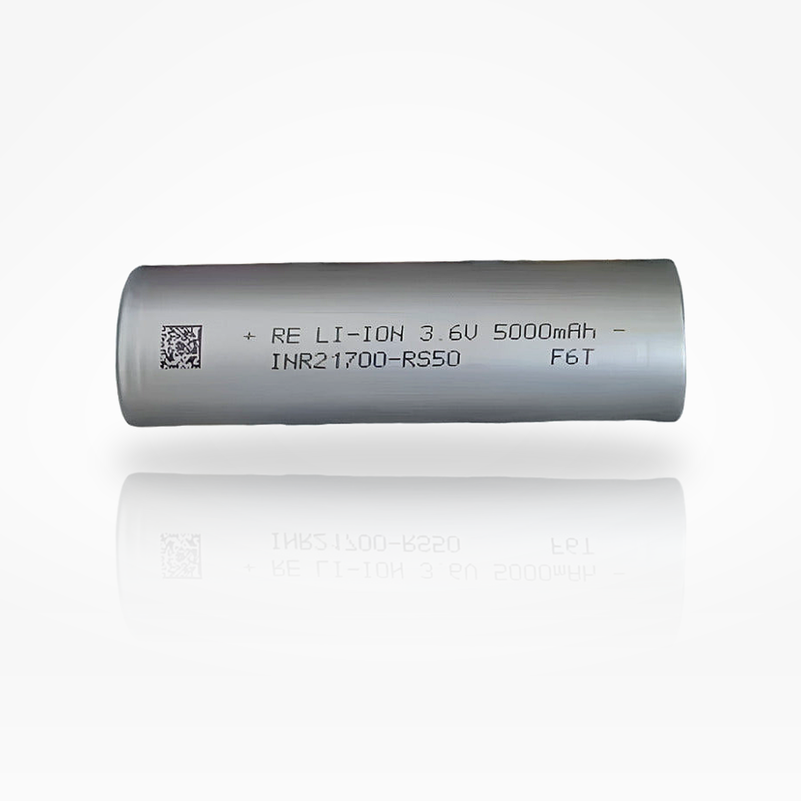


Reliance RS50 21700
5000mAh / 70A Tabless
High-output 5.0Ah 21700 tabless lithium-ion cell designed for applications that need both high capacity and very high current support.
Reliance RS50 21700 5000mAh 70A Tabless Battery
The Reliance RS50 is a high-power 21700 tabless cell positioned for demanding pack designs that need a strong balance of energy, high-current capability, and low internal resistance. Its 5000mAh class capacity gives it runtime advantages over many pure power cells, while the 70A maximum continuous discharge rating is specified with an 80°C temperature cut-off condition.
the RS50 should be presented as a high-current cell that requires proper thermal validation. The 70A rating is powerful, but at the highest currents the specification allows discharge termination by voltage cut-off or temperature cut-off, meaning real delivered capacity depends heavily on cooling, enclosure design, cell state of charge, and pack resistance.
| Brand / Model | Reliance INR21700-RS50 |
|---|---|
| Cell Type | 21700 cylindrical rechargeable lithium-ion cell |
| Architecture | Tabless 21700 design |
| Product Capacity Class | 5000mAh |
| Minimum Standard Discharge Capacity | 4950mAh at 1.0A discharge to 2.5V after standard charge |
| Nominal Voltage | 3.6V |
| End-of-Charge Voltage | 4.20V |
| Discharge Cut-Off Voltage | 2.50V |
| Standard Charge | 2.5A CCCV to 4.20V, 100mA cut-off, 25±3°C |
| Rate Charge | 8A CCCV to 4.20V, 100mA cut-off, 25±3°C |
| Fast Charge | 15A CCCV to 4.20V, 100mA cut-off, 25±3°C |
| 15-Min Stepwise Charge | 10A for 2min, 16A for 3.5min, 20A for 7min, 10A for 2.5min to 4.0Ah / 80% SOC with 55°C protection temperature |
| Maximum Continuous Charge | 15A |
| Maximum Continuous Discharge | 70A with 80°C temperature cut-off Thermal validation required |
| AC Internal Resistance | ≤4.0mΩ at 1kHz |
| Operating Temperature | Charge: 0°C to 60°C; Discharge: -40°C to 80°C |
| Storage Temperature | 1 year: -20°C to 25°C; 3 months: -20°C to 45°C; 1 month: -20°C to 60°C |
| Shipment Voltage | 3.46V to 3.52V |
| Dimensions | 21.35mm max diameter × 70.30mm max height, with tube |
| Weight | ≤67.0g |
| Protection | No — unprotected bare cell; use pack-level or device-level protection |
Electrical operating envelope at a glance.
These quick-reference visuals summarize the RS50’s current layers, voltage window, capacity-to-energy translation, and C-rate interpretation.
1. Current Capability Stack
Key current reference points for standard charge, rate charge, fast charge, high-rate discharge, and max continuous discharge.
2. Voltage Operating Window
Basic per-cell voltage limits for charger, BMS, and system-control logic.
3. Capacity and Energy Translation
Nominal watt-hours are estimated from capacity class and nominal voltage.
4. C-Rate Conversion
The RS50 data sheet defines 1C as 5.0A.
| 1.0A | 0.2C standard discharge current |
|---|---|
| 2.5A | 0.5C standard charge current |
| 8A | 1.6C rate charge current |
| 15A | 3C fast charge / maximum continuous charge |
| 40A | 8C high-rate discharge and cycle-life test current |
| 70A | 14C maximum continuous discharge with 80°C temperature cut-off |
High-current output should be evaluated with voltage sag, heat rise, and temperature cut-off behavior in mind.
The RS50 rate-discharge table includes 1A, 10A, 20A, 30A, 40A, 50A, 60A, and 70A conditions. Relative capacity remains high through 50A, then drops sharply at 60A and 70A because the test may terminate at 2.5V or at the specified temperature cut-off. This makes the cell very strong for high-power use, but it also means high-current operation is fundamentally thermal-design dependent.
The simplified discharge-curve graph below visualizes voltage versus delivered capacity under light, high, and extreme-current conditions. It is intentionally simplified for product-page readability and is not a digitized laboratory discharge trace.
Rate capability summary
| 1A | 100% relative capacity reference |
|---|---|
| 10A | ≥96% relative capacity |
| 20A | ≥96% relative capacity |
| 30A | ≥95% relative capacity |
| 40A | ≥95% relative capacity |
| 50A | ≥90% relative capacity |
| 60A | ≥60% relative capacity |
| 70A | ≥50% relative capacity under 2.5V or 80°C cut-off condition |
5. Simplified Discharge-Curve Graph
Voltage vs. capacity illustration for 1A, 40A, 50A, and 70A operation. Simplified for product-page visualization.
6. Estimated IR Voltage Drop
Using the published ≤4mΩ ACIR as an order-of-magnitude planning reference. Actual DC sag includes the full pack current path.
7. Rate Capability Bar Chart
Minimum relative capacity by discharge current under the specified rate-discharge test.
8. Tabless Current-Path Concept
Simplified educational diagram showing why tabless-style cells are attractive in high-current applications.
Charge, temperature, cycle life, and storage should be managed as one system.
The RS50 specification includes standard charge, rate charge, fast charge, 15-minute stepwise fast charge, temperature discharge, cycle-life, and storage criteria. These condensed charts make the major operating limits easier for customers to understand.
9. Charge Profile Reference
Standard charge, rate charge, and fast charge all use CCCV to 4.20V with 100mA cut-off under stated conditions.
10. 15-Minute Stepwise Fast Charge Map
Specification-defined stepwise charge to 4.0Ah / 80% SOC with 4.20V protection voltage and 55°C protection temperature.
11. Thermal Operating Envelope
Published cell-surface operating ranges.
12. Temperature Discharge Capacity
Relative capacity at 40A discharge after 8A rate charge, normalized to 25°C.
13. Cycle-Life Visualization
Published capacity-retention criteria under cold and room-temperature cycle test profiles.
14. Storage Performance & Shipment Voltage
Published storage and ex-factory conditions.
| Shipment Voltage | 3.46V to 3.52V |
|---|---|
| 1-Year Storage | -20°C to 25°C |
| 3-Month Storage | -20°C to 45°C |
| 1-Month Storage | -20°C to 60°C |
| 30-Day Hot Storage | After 60±3°C storage, retained capacity ≥80% and recovered capacity ≥90% under the stated test method. |
21700 dimensional envelope for holders, tab welding fixtures, and pack CAD.
Mechanical fit is especially important in dense high-current packs. Use the maximum envelope for holder clearance, weld fixture design, insulation planning, and battery-pack CAD.
15. Cell Dimension Diagram
Mechanical envelope based on the RS50 specification with tube.
16. Pack Scaling Formulas
Quick math for series/parallel planning. Validate current limits thermally and electrically.
Pack Voltage ≈ Series Count × 3.6V
Pack Capacity ≈ Parallel Count × 5.0Ah
Pack Energy ≈ S × P × 18.0Wh
Cell-Level Current Reference ≈ P × 70A
17. Example Parallel Scaling
Approximate scaling using cell-level 70A rating with 80°C cut-off condition, not a finished-pack guarantee.
| 1P | 5.0Ah, 18.0Wh, 70A cell-level current reference |
|---|---|
| 2P | 10.0Ah, 36.0Wh, 140A cell-level current reference |
| 3P | 15.0Ah, 54.0Wh, 210A cell-level current reference |
| 4P | 20.0Ah, 72.0Wh, 280A cell-level current reference |
| 5P | 25.0Ah, 90.0Wh, 350A cell-level current reference |
18. Common Series Voltage Examples
Nominal voltage examples only. Full-charge and cut-off pack voltages scale separately.
| 1S | 3.6V nominal / 4.2V full / 2.5V cut-off |
|---|---|
| 3S | 10.8V nominal / 12.6V full / 7.5V cut-off |
| 4S | 14.4V nominal / 16.8V full / 10.0V cut-off |
| 5S | 18.0V nominal / 21.0V full / 12.5V cut-off |
| 10S | 36.0V nominal / 42.0V full / 25.0V cut-off |
| 13S | 46.8V nominal / 54.6V full / 32.5V cut-off |
Use the RS50 inside a temperature-monitored, current-limited electrical system.
This is a high-power unprotected cell. Proper implementation requires pack-level protection and host-device control for voltage, current, temperature, and short-circuit fault conditions.
19. Suggested Control Threshold Map
System-level control guidance derived from the RS50 specification.
| Charge upper limit | 4.20V per cell |
|---|---|
| Discharge floor | 2.50V per cell |
| Standard charge | 2.5A CCCV to 4.20V, 100mA termination |
| Rate charge | 8A CCCV to 4.20V, 100mA termination |
| Fast charge / max charge | 15A CCCV to 4.20V, 100mA termination |
| Charge temperature gate | 0°C to 60°C |
| Discharge temperature gate | -40°C to 80°C |
| Protection requirements | Pack and host should include over-charge, over-discharge, over-current, over-heat, and short-circuit protection. |
20. Risk-Control Checklist
Recommended pack-building and use practices.
- Use only in devices or packs designed for high-current 21700 lithium-ion cells.
- Use a BMS or controller that monitors voltage, current, and cell temperature.
- Do not charge above 4.20V or discharge below 2.50V per cell.
- Validate high-current operation under the actual enclosure, cooling, and load profile.
- Never carry loose cells with conductive objects such as keys, coins, tools, or metal cases.
- Spot weld for pack assembly; do not solder directly to the cell body.
- Inspect wraps and top insulator rings before use.
- Size busbars, nickel, tabs, fuses, wiring, and BMS MOSFETs for both electrical resistance and heat rise.
Best suited for high-power systems where current density and runtime both matter.
Power Tools
- Strong candidate for high-output tool packs with heavy current draw.
- Tabless design and low ACIR support high-power operation when pack construction is robust.
Drones / RC
- Useful where burst current, voltage support, and compact energy are all important.
- Thermal validation is essential at very high discharge currents.
E-Bike / Mobility
- Suitable for performance mobility packs when paired with proper BMS, fusing, and cooling.
- Parallel count should be selected from measured current, voltage sag, and heat rise.
Robotics
- Supports high motor current in compact autonomous or remote-controlled systems.
- Useful for platforms that need both energy capacity and high power response.
High-Output Lighting
- Appropriate for demanding LED systems that pull high current from each cell.
- Use only in devices designed for unprotected 21700 flat-top cells.
Custom Battery Packs
- Designed for experienced builders and integrators who can manage current sharing and heat.
- Requires matched cells, correct welding, insulation, protection electronics, and pack-level testing.
21. Selection Bias: Power vs. Runtime
for shoppers comparing high-power and high-energy cells.
22. Application Suitability Matrix
Simple product-page fit guidance.
| Power tools | Strong fit |
|---|---|
| Drones / RC | Strong fit with validation |
| Performance mobility packs | Strong fit with BMS and thermal design |
| Runtime-focused electronics | Good, but may be more power than needed |
| Maximum energy per cell only | Compare against energy-focused cells |
| Unmanaged consumer devices | Not recommended |
Safety, Handling & Compatibility Notice
This product is an unprotected lithium-ion cell. It should only be used by customers who understand lithium-ion cell safety and who are using the battery in compatible hardware, managed packs, or professionally designed assemblies. Improper use can lead to overheating, venting, fire, or explosion.
- Charge only with lithium-ion chargers or managed battery systems designed for the correct chemistry and cell count.
- Never short circuit, crush, puncture, incinerate, or expose the cell to water.
- Do not use cells with damaged wraps, dented cans, or missing top insulator rings.
- Do not mix with cells of different age, capacity, model, or state of charge in the same pack.
- For assembly, use spot welding rather than direct soldering to reduce heat damage risk.
- Store and transport in non-conductive cases; never carry loose cells in pockets or bags.
- Keep away from children and from applications for which the product is not specified.
- Not for e-cigarette, vape, or similar use.
Common technical questions about the Reliance RS50.
What is the capacity of the Reliance RS50?
The product is sold as a 5000mAh-class cell. The specification lists a minimum standard discharge capacity of 4950mAh under the standard charge and 1.0A discharge test method.
What is the discharge rating?
The specification lists a maximum continuous discharge current of 70A with an 80°C temperature cut-off. At 70A, real delivered capacity depends heavily on cooling, enclosure design, and whether voltage or temperature cut-off occurs first.
Why does the 70A relative capacity look lower than 40A or 50A?
The rate-discharge test allows termination at 2.5V or at the temperature cut-off. At 60A and 70A, heat rise can limit delivered capacity before the full low-current capacity is reached.
Is this a protected battery?
No. This is an unprotected bare 21700 cell and should be used only in equipment or packs with appropriate voltage, current, short-circuit, and temperature protection.
What charger should be used?
Use a lithium-ion charger or battery-management system that uses a CCCV profile to 4.20V per cell. The standard charge current is 2.5A, while the specification also defines 8A rate charge and 15A fast charge under stated conditions.
Can the RS50 fast charge?
Yes, the specification defines 15A fast charge and a 15-minute stepwise fast-charge profile to 4.0Ah / 80% SOC. Fast charging requires strict temperature control and should be validated in the final product.
What is the correct discharge cut-off voltage?
The specification states a 2.50V discharge cut-off voltage per cell. Many pack designers choose a higher system cut-off to reduce stress and improve service life.
Can the RS50 be used in battery packs?
Yes. It is well suited to high-power custom battery packs when cell matching, spot welding, thermal monitoring, fusing, BMS sizing, insulation, and current sharing are properly engineered.
Can I solder wires directly to this cell?
Direct soldering is not recommended. Spot welding is the preferred pack-assembly method because it reduces the risk of heat damage to the cell.
What are the cell dimensions?
The published maximum dimensions are 21.35mm diameter and 70.30mm height, with the outer tube included. Always confirm fit in the actual device, holder, or pack fixture.
What temperature range is allowed?
The specification lists 0°C to 60°C for charging and -40°C to 80°C for discharging, measured at the cell surface. High-current designs should monitor temperature and derate current as needed.
What does ≤4mΩ ACIR mean?
It indicates very low AC internal resistance at 1kHz, which supports high-current behavior and helps reduce voltage sag. Real pack resistance also includes welds, nickel, busbars, wiring, fuses, holders, and BMS components.
How many cycles should I expect?
The specification includes several cycle criteria, including ≥60% capacity retention after 400 cycles under room-temperature 40A discharge and ≥60% after 400 cycles under a 15A charge / 30A discharge profile. Actual service life depends on charge rate, discharge current, temperature, depth of discharge, and pack design.
What is the shipment voltage?
The specification states that the cell should ship between 3.46V and 3.52V.
Can I carry this battery loose?
No. Loose transport is unsafe because conductive objects can short the terminals. Always use a non-conductive battery case.