
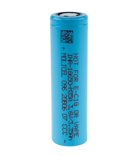
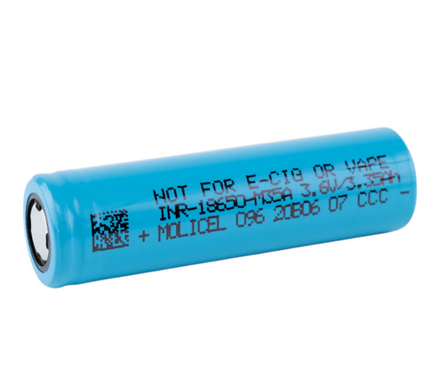
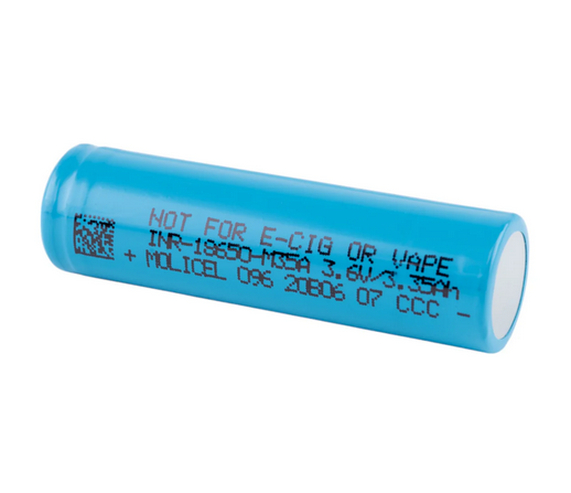


Molicel M35A 18650
3500mAh / 10A
High-capacity 18650 lithium-ion energy cell designed for long runtime, reliable moderate-current output, and compact pack integration.
Molicel M35A 18650 3500mAh 10A Battery
The Molicel M35A is an energy-focused 18650 cell for applications that need longer runtime than high-drain power cells while retaining a practical 10A maximum discharge capability. Its technical profile is best suited to protected battery packs, flashlights, power banks, backup modules, portable electronics, medical/industrial devices, and moderate-drain custom assemblies.
Molicel product data sheet lists 3450mAh typical and 3350mAh minimum. .
| Brand / Model | Molicel INR-18650-M35A |
|---|---|
| Cell Type | 18650 cylindrical lithium-ion rechargeable cell |
| Product Listing Capacity | 3500mAh class |
| Data-Sheet Typical Capacity | 3450mAh / 12.5Wh |
| Minimum Capacity | 3350mAh / 11.9Wh |
| Nominal Voltage | 3.6V |
| Charge Cut-Off Voltage | 4.20V |
| Discharge Cut-Off Voltage | 2.50V |
| Standard / Max Charge | 1.7A CC-CV charge, 2.5 hour standard charge time |
| Max Discharge Current | 10A maximum continuous discharge-current specification |
| Operating Temperature | Charge: 0°C to 60°C; Discharge: -40°C to 60°C |
| Energy Density | 730Wh/L volumetric and 264Wh/kg gravimetric in product data sheet v1.4 |
| Dimensions | 18.6mm max diameter × 65.2mm max height |
| Weight | 48g max |
| Protection | No — unprotected bare cell. Use device-level or pack-level protection. |
Electrical operating envelope at a glance.
These quick-reference visuals summarize the cell’s operating window, current limits, capacity-to-energy translation, and C-rate interpretation.
1. Current Capability Stack
Charge and discharge reference points on a 0–10A scale.
2. Voltage Operating Window
Recommended pack logic should keep the cell within this basic CC-CV charge and discharge range.
3. Capacity and Energy Translation
Nominal watt-hours are calculated from amp-hours and nominal voltage.
4. C-Rate Conversion
For a 3450mAh typical cell, 1C equals approximately 3.45A.
| 0.68A | ≈0.2C reference discharge curve |
|---|---|
| 1.7A | ≈0.5C standard / maximum charge |
| 3.4A | ≈1C discharge curve reference |
| 4A | Cycle-characteristic discharge curve reference |
| 8A | Higher-stress cycle-characteristic discharge curve reference |
| 10A | ≈2.9C maximum discharge specification |
Runtime-focused output with a 10A cell-level ceiling.
The M35A data-sheet discharge curves include 0.68A, 1.7A, 3.4A, and 10A traces at 23°C. As current increases, the voltage plateau shifts downward and delivered capacity may decrease because of voltage sag and thermal stress. That makes the M35A a strong runtime cell for moderate loads, but not a replacement for high-power cells like the P28A, P30B, P45B, or similar high-current designs.
Discharge-rate positioning
| Low-load range | Best capacity utilization and highest voltage plateau |
|---|---|
| Moderate range | Good runtime and practical output for flashlights and portable electronics |
| 10A max range | Cell-level maximum rating; requires heat and voltage-sag validation |
| Selection takeaway | Use the M35A when runtime matters more than peak current. |
5. Simplified Discharge-Curve Graph
Voltage vs. capacity illustration for 0.68A, 1.7A, 3.4A, and 10A discharge at 23°C. Simplified for product-page visualization.
6. Estimated Power Output
Approximate nominal watts using 3.6V nominal voltage. Actual output varies with voltage sag and state of charge.
Thermal conditions strongly affect discharge capacity and cycle life.
The current product data sheet includes charge, discharge-rate, discharge-temperature, and cycle-characteristic curves. These visuals summarize the main trends for product-page education.
7. Charge Profile Reference
Standard charge: 1.7A CC-CV to 4.2V with 100mA cut-off at 23°C.
8. Temperature Operating Envelope
Published ambient temperature ranges for charge and discharge.
9. Discharge Temperature Characteristics
Simplified capacity trend from the data-sheet temperature curve family.
10. Cycle-Life Visualization
Simplified visual based on data-sheet cycle curves for 4A, 6A, and 8A discharge.
18650 dimensional envelope for holders, sleds, weld fixtures, and pack CAD.
Use the maximum data-sheet dimensions for enclosure planning and fixture clearances, not just nominal 18 × 65mm sizing.
11. Cell Dimension Diagram
Mechanical envelope based on the current Molicel data sheet.
12. Pack Scaling Formulas
Quick math for series/parallel planning using typical capacity.
Pack Voltage ≈ Series Count × 3.6V
Pack Capacity ≈ Parallel Count × 3.45Ah
Pack Energy ≈ S × P × 12.5Wh
Pack Current Ceiling ≈ Parallel Count × 10A
13. Example Parallel Scaling
Approximate scaling, assuming balanced cells and proper thermal/electrical design.
| 1P | 3.45Ah, 12.5Wh, 10A cell-level ceiling |
|---|---|
| 2P | 6.90Ah, 25.0Wh, 20A cell-level ceiling |
| 3P | 10.35Ah, 37.5Wh, 30A cell-level ceiling |
| 4P | 13.80Ah, 50.0Wh, 40A cell-level ceiling |
| 5P | 17.25Ah, 62.5Wh, 50A cell-level ceiling |
14. Common Series Voltage Examples
Nominal voltage examples only. Full-charge and cut-off pack voltages scale separately.
| 1S | 3.6V nominal / 4.2V full / 2.5V cut-off |
|---|---|
| 3S | 10.8V nominal / 12.6V full / 7.5V cut-off |
| 4S | 14.4V nominal / 16.8V full / 10.0V cut-off |
| 5S | 18.0V nominal / 21.0V full / 12.5V cut-off |
| 10S | 36.0V nominal / 42.0V full / 25.0V cut-off |
| 13S | 46.8V nominal / 54.6V full / 32.5V cut-off |
Use the M35A inside a controlled electrical and thermal system.
This is an unprotected high-energy cell. Safe implementation requires a charger/BMS strategy that respects the voltage and temperature boundaries, along with pack-level overcurrent and short-circuit protection.
15. Suggested Control Threshold Map
System-level control guidance derived from the published operating range.
| Charge upper limit | 4.20V per cell |
|---|---|
| Discharge floor | 2.50V per cell |
| Charge current | 1.7A standard / maximum continuous charge current |
| Discharge current | 10A maximum cell-level discharge specification |
| Charge temperature gate | Allow 0°C to 60°C cell ambient range |
| Discharge temperature gate | Allow -40°C to 60°C cell ambient range; derate heavily in cold conditions |
16. Risk-Control Checklist
Recommended pack-building and use practices.
- Use only in devices or packs designed for lithium-ion 18650 cylindrical cells.
- Use a charger/BMS that monitors voltage, current, and temperature.
- Do not charge above 4.20V or discharge below 2.50V per cell.
- Do not exceed 10A per cell without application-specific validation and thermal margin.
- Never carry loose cells with conductive objects such as keys, coins, or tools.
- Spot weld for pack assembly; do not solder directly to the cell body.
- Inspect wraps and top insulator rings before use.
- Validate pack busbar, nickel, wiring, fuse, BMS, and enclosure design under real load.
Best suited for long-runtime, moderate-current systems.
Flashlights
- Excellent for runtime-focused 18650 lights.
- Best in devices that do not exceed the 10A cell-level envelope.
Power Banks
- High energy density for compact portable power.
- Works well where sustained current is moderate.
Battery Packs
- Useful for custom packs where energy per cell matters.
- Requires matching, BMS, fusing, and thermal validation.
Medical / Industrial
- Reliable runtime for controlled-load equipment.
- Requires validated charging and protection circuitry.
Backup Modules
- Appropriate for standby or moderate-duty backup systems.
- Consider storage voltage and operating temperature.
Consumer Electronics
- Good for laptops, wireless modules, and moderate-drain electronics.
- Not intended for unmanaged high-current use.
17. Selection Bias: Runtime vs. Power
for shoppers comparing high-energy and high-power cells.
18. Application Suitability Matrix
Simple product-page fit guidance.
| Runtime flashlights | Strong fit |
|---|---|
| Power banks | Strong fit |
| Backup modules | Strong fit |
| Custom battery packs | Validate current |
| High-current tools | Use higher-drain cell |
| Vape / e-cigarettes | Prohibited |
Safety, Handling & Compatibility Notice
This product is an unprotected lithium-ion cell. It should only be used by customers who understand cell-level lithium-ion safety and who are using the battery in compatible hardware, managed packs, or professionally designed assemblies. Improper use can lead to overheating, venting, fire, or explosion.
- Charge only with lithium-ion chargers or managed battery systems designed for the correct chemistry and cell count.
- Never short circuit, crush, puncture, incinerate, or expose the cell to water.
- Do not use cells with damaged wraps, dented cans, or missing top insulator rings.
- Do not mix with cells of different age, capacity, model, or state of charge in the same pack.
- For assembly, use spot welding rather than direct soldering to reduce heat damage risk.
- Store and transport in non-conductive cases; never carry loose cells in pockets or bags.
- Keep away from children and from applications for which the product is not specified.
- Not for e-cigarette, vape, or similar use.
Common technical questions about the Molicel M35A.
Is the Molicel M35A a 3500mAh or 3450mAh battery?
The live product listing markets it as 3500mAh. The current Molicel data sheet lists 3450mAh typical and 3350mAh minimum. The page presents both clearly.
What is the maximum discharge rating?
The Molicel data sheet lists a maximum continuous discharge current of 10A. Finished pack ratings must be derated and validated.
Is this a protected battery?
No. The M35A is an unprotected flat-top 18650 cell. Use it only with compatible device-level or pack-level protection.
What charger should be used?
Use a lithium-ion charger or battery-management system that charges to 4.20V per cell using a CC-CV profile. The standard and maximum continuous charge current is 1.7A.
What is the discharge cut-off voltage?
The data sheet lists a 2.50V discharge cut-off voltage. Many pack designers use a higher practical cut-off to reduce stress and improve cycle life.
Is the M35A good for high-drain devices?
It is a high-capacity, moderate-drain cell. For sustained currents above 10A per cell, choose a higher-power cell such as a P-series Molicel or another high-drain model.
Can the M35A be used in battery packs?
Yes. It is well suited to runtime-focused custom packs when cell matching, spot welding, protection electronics, and thermal validation are properly handled.
Can I solder wires directly to this cell?
Direct soldering is not recommended. Spot welding is the preferred pack-assembly method because it reduces the risk of heat damage to the cell.
What are the cell dimensions?
The published maximum dimensions are 18.6mm diameter and 65.2mm height, with a maximum weight of 48g.
What temperature range is allowed?
The data sheet lists 0°C to 60°C for charging and -40°C to 60°C for discharging. Cold-temperature discharge has reduced capacity and should be derated.
How many watt-hours does one cell provide?
The M35A data sheet lists 12.5Wh typical energy and 11.9Wh minimum energy.
Can I use this in e-cigarettes or vaporizers?
No. Molicel’s current data sheet explicitly prohibits use in e-cigarettes, vaporizers, vape/mod devices, and applications not permitted by Molicel terms and specifications.
Can I carry this battery loose?
No. Loose transport is unsafe because conductive objects can short the terminals. Always use a non-conductive battery case.