
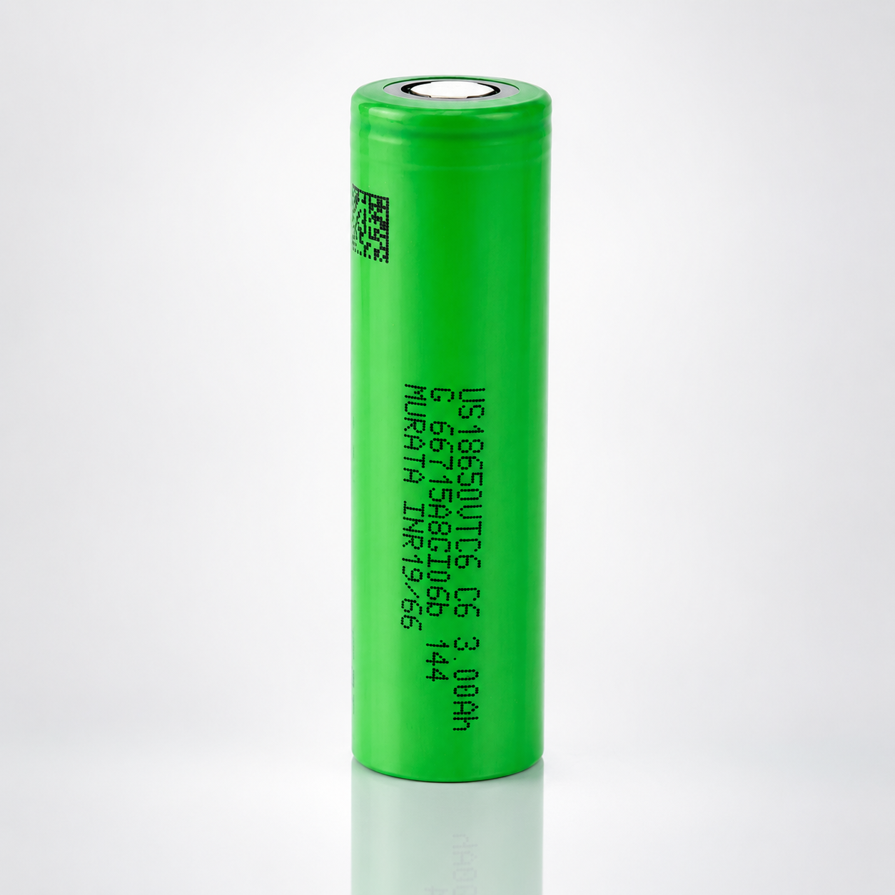
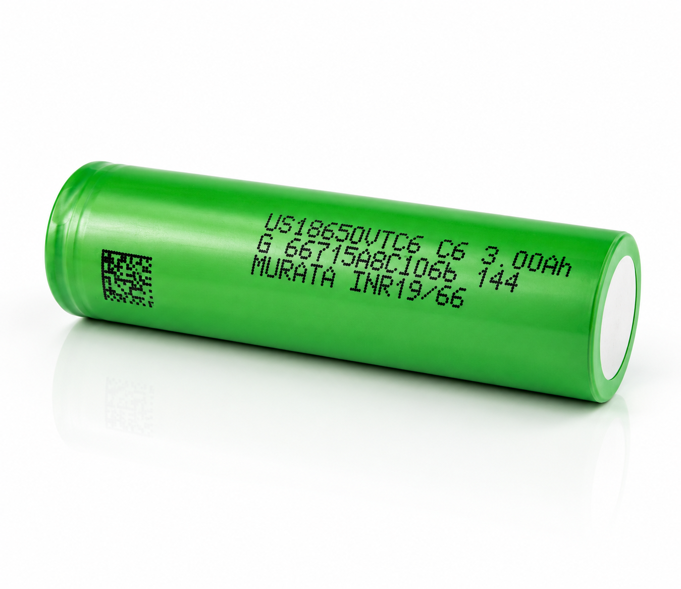
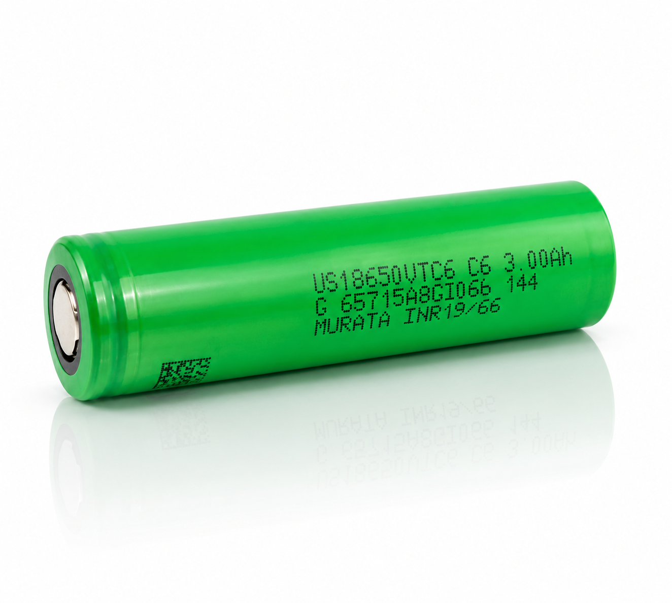


Sony | Murata VTC6 18650
3000mAh / 15A CDR
A professional flat-top lithium-ion cell built for systems that require a strong combination of 3000mAh-class runtime, high-current delivery, compact 18650 fitment, and repeatable pack integration.
US18650VTC6: compact high-drain energy for professional 18650 systems.
The Sony | Murata VTC6 is positioned as a high-drain 18650 cell for applications that need more runtime than many ultra-high-power cells while still supporting a 15A continuous discharge design rating. It is suited for high-output flashlights, robotics, power modules, test equipment, and engineered battery packs where thermal management and protection electronics are part of the system design.
| Core Parameter | Technical Value |
|---|---|
| Manufacturer / Model | Sony | Murata US18650VTC6 |
| Cell Format | 18650 cylindrical, flat top, unprotected lithium-ion cell |
| Capacity Class | 3000mAh customer-facing class; 3000mAh rated minimum capacity |
| Nominal Capacity | 3120mAh under 0.2 ItA reference discharge to 2.0V at 23°C |
| Nominal Voltage | 3.6V |
| Charge Voltage / Method | CC-CV to 4.20V; data-sheet charge reference is 3.0A with 150mA cut-off |
| Discharge Design Rating | 15A continuous per product listing; 30A is temperature-limited characterization, not a no-derating continuous rating |
| Cut-off Reference | 2.5V cut-off for higher-current data-sheet discharge curves; 2.0V cut-off for low-current capacity rating test |
| Dimensions | With tube: 18.5mm maximum diameter × 65.2mm maximum length |
| Protection Circuit | None. Requires compatible device-level or pack-level protection. |
Voltage, charge profile, and current-control operating window.
Use these visuals as a product-page engineering reference. Final pack design should be validated against the latest Murata product specification, BMS limits, interconnect resistance, enclosure airflow, and the application duty cycle.
Cell Voltage Window
Single-cell endpoints for charge and discharge control. High-load designs commonly terminate near 2.5V.
CC-CV Charge Profile
Reference profile: 3.0A constant-current charge to 4.20V, followed by CV taper to 150mA.
Current Capability Map
Separate design rating from data-sheet characterization conditions.
C-Rate Translation
Based on a 3.0Ah rated capacity class.
High-current discharge requires temperature-aware design.
The VTC6 data sheet characterizes 3A, 5A, 10A, 15A, 20A, and 30A discharge curves. As current increases, voltage sag and surface temperature rise become more important, especially in sealed enclosures or dense parallel groups.
Simplified Discharge-Curve Family
Illustrative curve shape based on the manufacturer-style discharge graph; actual voltage depends on temperature, cell age, contact resistance, and load profile.
Thermal Risk Ladder
Higher current increases surface-temperature rise; 30A characterization uses thermal cut-off logic.
Capacity is specified at low current; high-current runtime depends on cutoff and heat.
Capacity Reference Stack
How the 3000mAh product rating relates to the Murata nominal-capacity value.
Cycle-Life Trend
Approximate visualized trend from the 500-cycle data-sheet chart under 4A charge / 10A discharge test conditions.
18650 flat-top fitment, insulation, and pack spacing.
Dimensional Envelope
Maximum dimensions with tube from Murata product data sheet.
| Mechanical Item | Design Guidance |
|---|---|
| Diameter | Use 18.5mm maximum with tube for fitment checks. |
| Length | Use 65.2mm maximum with tube; verify spring compression and terminal reach. |
| Top Style | Flat top. Device must be compatible with flat-top terminals. |
| Wrapper / Ring | Inspect PVC wrap and positive terminal insulator before every use. |
| Pack Assembly | Use correct spot-welded interconnects. Do not solder directly to cell terminals. |
| Thermal Path | Provide spacing, heat spreading, airflow, or derating for high-current duty cycles. |
Series and parallel scaling formulas for battery-pack planning.
The VTC6 can be used in professionally engineered battery packs when cells are matched, protected, mechanically restrained, and thermally controlled. The equations below are first-pass planning references before BMS derating and safety validation.
Vnom = S × 3.6VNominal pack voltage from series cell count.
Capacity = P × 3.0AhRated capacity estimate from parallel count.
Icont = P × 15ACell-level current before pack-level thermal derating.
Energy = S × P × 10.8WhRated energy estimate using 3.0Ah × 3.6V.
Where the VTC6 makes sense.
High-Output Flashlights
Strong fit for compact lights needing high current capability with 3000mAh-class runtime.
Robotics & RC Systems
Useful where bursts and moderate-high continuous loads are managed with proper pack protection.
Portable Power Modules
Good candidate for engineered 18650 modules where parallel groups keep current per cell controlled.
Tool & Instrument Packs
Supports compact high-current packs when the current, heat, and cut-off limits are validated.
Test Fixtures
Useful in battery holders and lab systems with measured current draw and suitable protection circuitry.
Professional Pack Builds
Appropriate only for builders using cell matching, spot welding, insulation, fusing, and BMS controls.
Embedded Electronics
Can be integrated into protected finished products with charge, discharge, and temperature safeguards.
Not For Loose Use
This bare cell must be carried in a case and used only in compatible protected devices or packs.
Sony | Murata VTC6 specification reference.
| Specification | Value / Note |
|---|---|
| Model | US18650VTC6 |
| Manufacturer | Sony | Murata |
| Cell Type | Rechargeable lithium-ion cylindrical cell |
| Size | 18650 |
| Top Style | Flat top |
| Protection | Unprotected bare cell; external protection is required in device or pack design |
| Nominal Capacity | 3120mAh under 0.2 ItA / 600mA discharge to 2.0V at 23°C after CCCV charge |
| Rated Minimum Capacity | 3000mAh under the same low-current reference condition |
| Nominal Voltage | 3.6V |
| Charge Voltage | 4.20V reference charge voltage |
| Standard Charge Reference | CC-CV, 3.0A, 4.20V, 2.5h, 150mA cut-off, 23°C reference condition |
| Continuous Discharge Rating | 15A product-page design rating |
| High-Current Data-Sheet Curves | 3A, 5A, 10A, 15A, 20A, and 30A discharge curves are characterized to 2.5V cut-off or 80°C surface-temperature cut-off |
| Discharge Cut-off Reference | 2.5V for high-current discharge curves; 2.0V for low-current nominal/rated capacity test |
| Weight | 46.6g typical |
| Dimensions With Tube | 18.5mm maximum diameter × 65.2mm maximum length |
| Cycle-Life Reference | Data-sheet chart shows 500-cycle characterization under 4A CC-CV charge and 10A discharge test conditions |
| Assembly Method | Do not solder directly to the cell; use properly designed spot-welded interconnects |
Professional lithium-ion handling requirements.
Required Practices
- Use only with a charger designed for 4.20V lithium-ion cells.
- Keep current, voltage, and temperature within manufacturer limits.
- Use an appropriate BMS or protection circuit in battery packs.
- Store and transport cells in protective cases, never loose with metal objects.
- Inspect wrappers, positive terminal insulators, and terminal rings before every installation.
- Use proper spot welding for pack assembly; avoid heat damage to terminals.
Do Not
- Do not short-circuit, overcharge, over-discharge, crush, puncture, or incinerate.
- Do not use a cell with damaged wrap, denting, leakage, rust, or abnormal heat.
- Do not mix old and new cells, different models, or mismatched state-of-charge groups.
- Do not solder directly to the cell body or terminals.
- Do not leave cells charging unattended or on combustible surfaces.
- Do not use in any device that exceeds the cell's current, thermal, or voltage envelope.
Sony | Murata VTC6 FAQ
Is the VTC6 a 15A or 30A battery?
Use 15A as the continuous product-page design rating. The 30A figure should be treated as a temperature-limited data-sheet characterization point that requires thermal supervision and is not a no-derating continuous rating.
Why does the data sheet list 3120mAh if the product is sold as 3000mAh?
3000mAh is the rated minimum capacity class. Murata's product data sheet also lists a 3120mAh nominal capacity under a low-current 0.2 ItA reference discharge condition.
Is this battery protected?
No. This is an unprotected bare 18650 cell. It does not include a built-in protection PCB, so the device or pack must provide over-charge, over-discharge, over-current, short-circuit, and thermal protection.
Is it flat top or button top?
This product is a flat-top 18650 cell. Confirm that your device is designed for flat-top unprotected 65mm-class cells before purchase.
What charger should I use?
Use a quality lithium-ion charger that supports CC-CV charging to 4.20V per cell. The data-sheet reference charge condition is 3.0A to 4.20V with current taper termination.
What discharge cut-off voltage should I use?
The data-sheet high-current discharge curves use 2.5V cut-off or thermal cut-off. The nominal/rated capacity test references 2.0V at low current, but practical high-load device designs should prevent over-discharge and follow the pack or device specification.
Can I use the VTC6 in a battery pack?
Yes, in properly engineered packs with matched cells, a suitable BMS, insulation, fusing where required, thermal design, and validated interconnects. It is not a drop-in replacement for a complete protected pack.
Can I solder directly to the cell?
No. Direct soldering can overheat the cell and damage internal safety structures. Pack assembly should use properly controlled spot welding and suitable nickel or nickel-plated interconnect material.
Can I mix VTC6 cells with other 18650 cells?
Do not mix models, ages, capacities, internal resistance values, or states of charge in a series or parallel pack. Use matched cells from the same model and similar production lot whenever possible.
What is the physical size?
Use the data-sheet envelope of 18.5mm maximum diameter and 65.2mm maximum length with tube for fitment planning. Tight devices should be checked before use.
Is the VTC6 good for high-output flashlights?
It can be a strong option for compatible high-output flashlights because it combines 3000mAh-class runtime with a 15A continuous discharge rating. Confirm the flashlight accepts flat-top unprotected cells.
Is this cell appropriate for e-cigarettes or vaporizers?
No. Follow the product-page safety warning and do not use this bare lithium-ion cell in e-cigarettes, vaporizers, or similar devices.
How should I store and carry loose cells?
Store cells in a cool, dry place and always carry them in an insulating battery case. Never carry loose cells in pockets, bags, or toolboxes where terminals can contact metal objects.
When should I stop using a cell?
Stop using the cell if the wrap is damaged, the top insulator is missing, the cell is dented, leaking, rusty, overheating, or showing abnormal voltage, capacity loss, or self-discharge.