
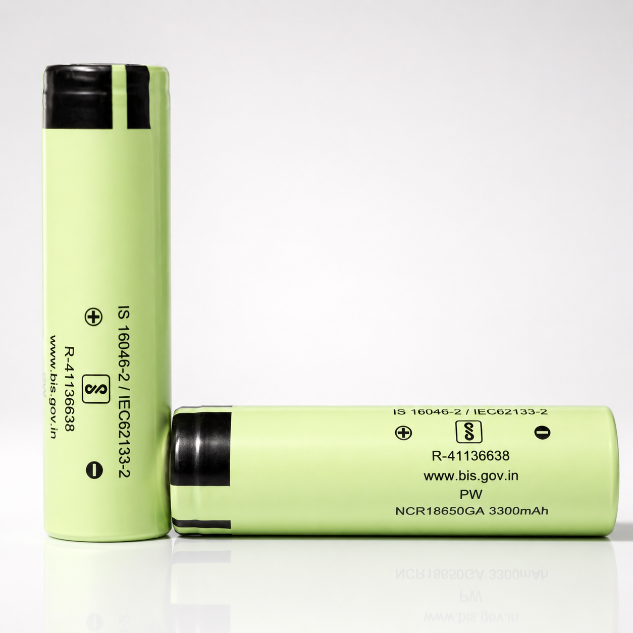
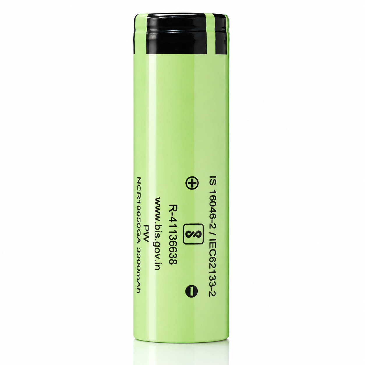
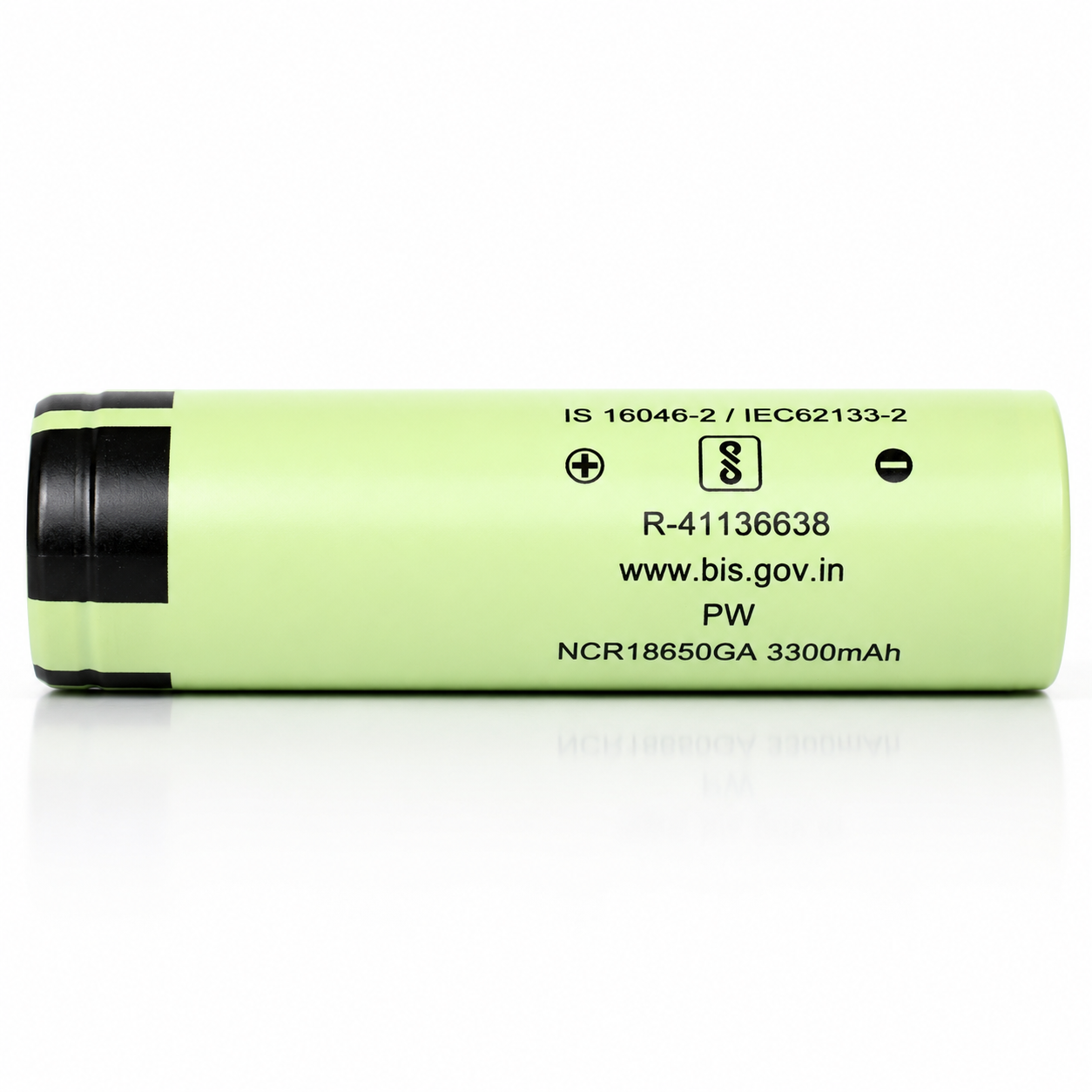
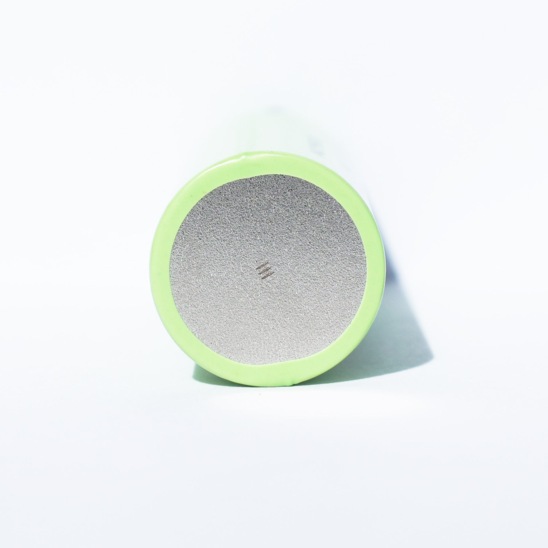


Panasonic NCR18650GA
3450mAh / 10A CDR
A high-energy 18650 lithium-ion cell engineered for long runtime, reliable moderate-current output, and scalable battery-pack integration in protected electronic systems.
Panasonic / Sanyo NCR18650GA: high-energy 18650 for runtime-focused pack builds.
The NCR18650GA is positioned as a high-capacity 18650 cell for applications that need more watt-hours per cell while keeping current demand within a controlled moderate-current design envelope. It is best used in engineered packs with appropriate BMS, thermal control, short-circuit protection, cell matching, and mechanical isolation.
| Core Parameter | Technical Value |
|---|---|
| Manufacturer / Model | Panasonic / Sanyo NCR18650GA, associated name GA6 |
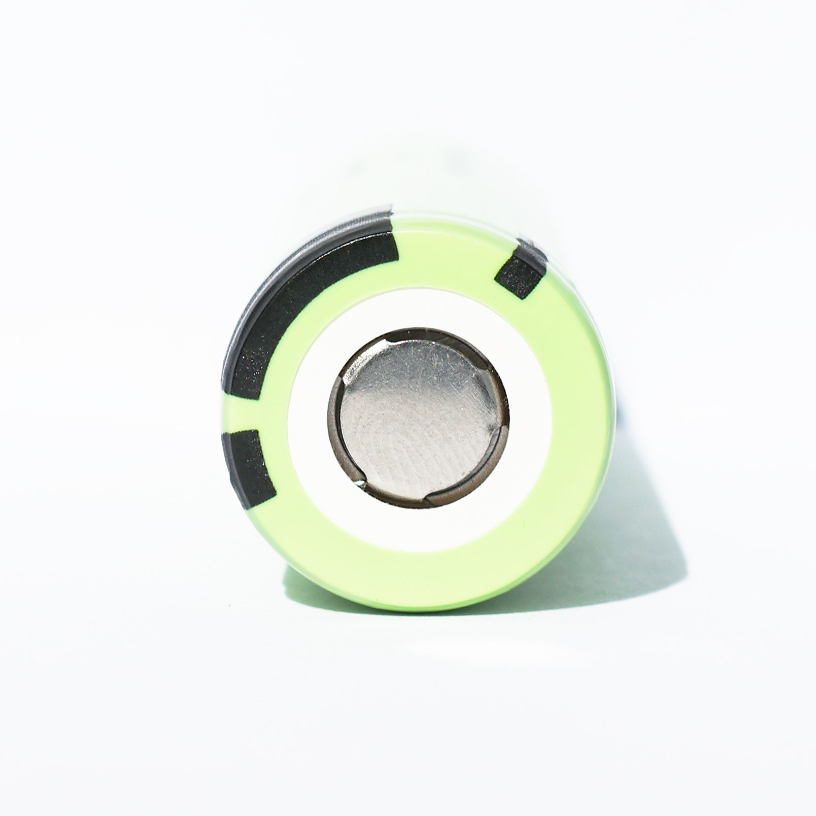
| Cell Format | 18650 cylindrical, flat top, unprotected lithium-ion cell |
| Typical Capacity | 3450mAh at 4.20V charge, reference value |
| Minimum Capacity | 3350mAh at 4.20V charge; 3235mAh at 4.15V charge |
| Rated Capacity | 3300mAh at 4.20V charge; 3190mAh at 4.15V charge |
| Nominal Voltage | 3.6V |
| Continuous Discharge | 10A maximum, specified for 0°C to +40°C discharge conditions |
| Charge Method | CC-CV to 4.20V; 1.675A standard charge current; 4.0 hour standard charge time |
| Dimensions | Approx. 18.33mm × 65.08mm listing; data-sheet drawing shows φ18.35±0.15mm × 65.05±0.25mm |
| Protection Circuit | None. Requires compatible device-level or pack-level protection. |
Voltage, current, and charge-control operating window.
Use these values as a product-page engineering reference. Final pack design should be validated against the latest manufacturer specification, pack protection electronics, thermal paths, enclosure airflow, and the actual application duty cycle.
Cell Voltage Window
Single-cell endpoints for charge and discharge control.
CC-CV Charge Profile
Standard charge is 1.675A CC to 4.20V, then CV taper; low-temperature current is reduced.
4.20V delivers maximum capacity; 4.15V is a reduced-voltage life-control option.
The data sheet specifies capacity at both 4.20V and 4.15V charge. Panasonic/Sanyo notes that reducing charge voltage can improve safety and cycle characteristics, with the trade-off of lower usable capacity per charge.
Capacity by Charge Voltage
mAh values from data-sheet capacity table.
Charge-Voltage Trade-Off
Approximate capacity retained versus the 4.20V typical capacity baseline.
Convert NCR18650GA C-rate values into practical design current.
The data sheet uses 3.35A as the 1C discharge test current and 1.675A as the standard 0.5C charge current. The cell's maximum continuous discharge rating is 10A per cell under specified thermal conditions.
C-Rate to Current Map
Reference currents derived from the 1C = 3.35A data-sheet basis.
Approximate Constant-Current Runtime
Idealized runtime using 3.45Ah typical capacity. Actual runtime varies by voltage sag, temperature, cut-off, age, and pack design.
Temperature limits are part of the electrical specification.
Continuous current, charge current, and voltage settings must be coordinated with cell-surface temperature. The manufacturer specification also states that maximum cell surface temperature must not exceed 70°C.
Charge Current vs. Temperature
Recommended charge-current regions from the data-sheet operating region.
Use & Storage Temperature Map
Data-sheet temperature ranges for charge, discharge, and storage.
Performance checkpoints for capacity, cycle life, and temperature behavior.
The following diagrams summarize selected electrical-characteristic criteria from the manufacturer specification. They are useful for comparing expected performance at controlled test conditions, not as a guarantee for every device or pack.
Discharge Time Criteria
Minimum discharge time at 25°C after full charge.
300-Cycle Criterion
After 300 charge/discharge cycles with 3.35A discharge to 2.5V at 25°C.
18650 flat-top dimensions for holders, sleds, and pack tooling.
Confirm fitment with your actual holder, nickel strip layout, insulation ring, wrap thickness, and pack compression system. Dimensional tolerances can matter in dense cell arrays.
Cell Dimensional Envelope
Based on data-sheet drawing and current product listing.
Mechanical Integration Checklist
Use before specifying holders, welded tabs, or dense parallel groups.
Translate one-cell specifications into pack-level electrical targets.
Series count determines voltage. Parallel count determines capacity and cell-current sharing. Always derate for BMS limits, connector rating, nickel/copper path resistance, fuse strategy, ambient temperature, enclosure airflow, and expected cell aging.
Vnom = S × 3.6VNominal pack voltage by series count.
Ah = P × 3.45AhTypical pack capacity by parallel count.
Wh ≈ S × P × 12.4WhApproximate typical energy per cell.
Imax = P × 10ACell-limited current before BMS and thermal derating.
Example Pack Scaling
Illustrative values before derating and BMS limits.
10S2P Reference Build
Example calculation for a 36V nominal class pack.
Best suited for long-runtime systems with controlled current demand.
The NCR18650GA is strongest when the product goal is energy density and runtime, while the pack designer keeps current per cell below the 10A maximum and manages temperature rise.
Battery Packs
Energy-dense 18650 packs with BMS, fusing, and thermal validation.
E-Bike / Mobility
Suitable for moderate-current packs with adequate parallel count and protection.
Power Banks
Long-runtime portable energy modules where output current is regulated.
Lighting Systems
High capacity for flashlights, work lights, and regulated LED packs.
Embedded Electronics
Runtime-focused instrumentation and field electronics.
Backup Power
Protected standby packs with conservative charge and storage controls.
Equipment Packs
Use only when the final device has proper certification and pack safeguards.
OEM Integration
For qualified pack builders using validated weld, BMS, and QA processes.
Unprotected lithium-ion cells require qualified handling and external protection.
This cell has no built-in protection circuit. The application, charger, or battery pack must provide protection against over-charge, over-discharge, over-current, reverse polarity, short circuit, excessive temperature, and mechanical abuse.
Critical Warnings
- Do not short circuit, overcharge, over-discharge, crush, puncture, incinerate, or expose to liquids.
- Do not use if the wrapper, insulator ring, terminal, or can is damaged.
- Do not mix old and new cells, different brands, different models, or different states of charge in the same pack.
- Do not store loose cells in a pocket, bag, drawer, or toolbox with conductive objects.
- Do not use with e-cigarette, vaporizer, or similar device.
- Use only within manufacturer-listed voltage, current, and temperature specifications.
Frequently asked technical questions.
Is the Panasonic NCR18650GA a protected battery?
No. This is an unprotected flat-top 18650 cell. It must be used only in a protected device or battery pack with proper BMS/protection circuitry.
What is the continuous discharge rating?
The continuous discharge rating is 10A maximum per cell under the manufacturer-specified temperature limits. Pack designs should apply additional derating.
Why does the listing say 3450mAh while the data sheet also lists 3300mAh and 3350mAh?
3450mAh is the typical capacity reference. The data sheet also lists a 3350mAh minimum capacity and a 3300mAh rated capacity at 4.20V charge.
What charger should be used?
Use a quality lithium-ion charger with CC-CV charging for 3.6V/3.7V Li-ion cells, 4.20V termination, and appropriate current control.
What is the standard charge current?
The standard charge current is 1.675A or less at standard temperature. The data sheet also specifies reduced low-temperature current of 0.838A or less from 0°C to +10°C.
Can this cell be charged to 4.15V instead of 4.20V?
Yes, the data sheet includes 4.15V charge-capacity values and recommends reduced charging voltage as a life-end control strategy. Capacity will be lower than at 4.20V.
What is the discharge cut-off voltage?
The data-sheet discharge end voltage is 2.5V. Device or pack protection should prevent over-discharge and should not rely on the cell alone.
Can I solder directly to this cell?
No. Direct soldering can damage the cell. Use properly controlled spot welding and pack assembly methods suitable for cylindrical lithium-ion cells.
What is the approximate energy per cell?
Using 3.6V nominal voltage and 3.45Ah typical capacity, the cell is approximately 12.4Wh before pack-level losses and derating.
Is this a high-drain cell?
No. It is best described as a high-capacity energy cell. For applications requiring sustained current above 10A per cell, select a higher-drain cell or increase parallel count.
What is the operating temperature range?
The data sheet lists charge operation at +10°C to +45°C for standard conditions and discharge operation from -20°C to +60°C. Temperature-specific current and voltage limits apply.
How should these cells be stored?
Store in a cool, dry, low-humidity environment, away from conductive objects. The data sheet gives storage temperature windows that become narrower as storage duration increases.
Can NCR18650GA cells be mixed with other 18650 cells?
No. Do not mix models, capacities, ages, brands, or states of charge. Battery packs should use matched cells from the same model and similar production lot where possible.
Will this fit every 18650 device?
Not always. This is a flat-top unprotected cell with approximate 18.33mm × 65.08mm listing dimensions. Confirm terminal style, physical fit, and protection requirements before use.
Is this cell appropriate for vaping or e-cigarettes?
No. The product warning states not to use this cell with e-cigarettes, vaporizers, or similar devices.
What does GA6 mean?
GA6 is an associated product/listing name for the NCR18650GA cell. The data sheet identifies the cell type as NCR18650GA.